in the centre of the float chamber cover,
without fouling the float. If the bar lifts the float
or if the float stands clear of the bar, bend the
float lever very slightly until the clearance is
correct (see illustration).
47 Later carburettors fitted with plastic floats
incorporate either a plain steel needle or a
spring-loaded needle enclosed in a plastic
sheath. The adjustment procedure for the
plain steel needle type is the same as
described in paragraph 46. Float level
adjustment for spring-loaded needles is as
follows.
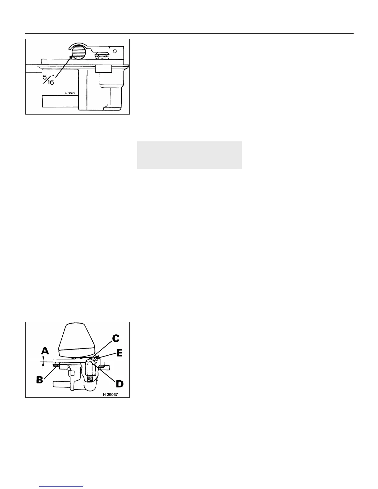
48 Invert the float chamber cover so that the
needle valve is closed but the spring is not
compressed. The gap between the float and
the flange on the float chamber cover, at the
centre of the cover, should be between 3.18
mm and 4.76 mm (see illustration). If the gap
is incorrect, bend the float lever slightly until
the specified gap is obtained. In the case of
floats having a moulded plastic hinge,
increase or decrease the washer thickness
under the needle seat to achieve the desired
float level height.
49 Place a new gasket in position on the float
chamber, refit the cover and secure it with the
three retaining screws.
50 Fill the carburettor piston damper with the
correct grade of oil, until the level is 13.0 mm
above the top of the hollow piston rod. Now
refit the damper plunger.
51 To obtain an initial jet setting and to allow
the engine to be started, screw the jet
adjusting nut up until the jet is flush with the
bridge in the carburettor body. Now screw the
nut down two complete turns on non-sealed
carburettors and three complete turns on
sealed units. Note: The sealed type
carburettors are identified by the throttle
adjusting screw which is recessed within the
carburettor body.
52 The carburettor can now be refitted to the
car as described in Section 12 and the idle
speed and mixture adjustments carried out as
described in Section 15.
14 Carburettor (SU HIF44 and
HIF38)) - fault diagnosis and
overhaul
3
Fault diagnosis
1 Refer to Section 13.
Overhaul
SU HIF44 carburettor
2 Remove the carburettor from the car as
described in Section 12, then clean the
exterior surfaces thoroughly and wipe dry.
3 Mark the float chamber cover in relation to
the carburettor body. Remove the screws,
and withdraw the cover and sealing ring (see
illustration).
4 Unscrew and remove the mixture screw
and spring, and withdraw the seal.
5 Unscrew the jet retaining screw, and
remove the spring.
6 Withdraw the jet and bi-metal lever
assembly. Disengage the lever from the jet.
7 Unscrew and remove the float pivot and
seal.
8 Withdraw the float and the needle valve.
9 Unscrew and remove the needle valve seat.
10 Unscrew and remove the piston damper,
and drain the oil.
11 Mark the dashpot in relation to the
carburettor body. Remove the screws and
withdraw the dashpot together with the
piston.
12 Prise the clip from the top of the piston
rod, then withdraw the piston and spring from
the dashpot.
13 Unscrew the needle retaining grub screw.
Remove the needle, guide and spring from the
piston.
14 From underneath the main body, unscrew
the jet bearing nut and withdraw the bearing.
15 Note how the spring is attached to the
fast idle cam lever, then bend back the
locktabs, unscrew the nut and remove the
washer.
16 Hold the return spring against the main
body, and use a screwdriver to prise the cam
lever from the end of the cold start spindle.
Remove the spring.
17 Remove the end cover and spindle seat.
18 Remove the two screws and withdraw the
retaining plate, cold start body and gasket.
19 Remove the O-ring from the end of the
cold start spindle, and withdraw the spindle
from the main body. Remove the cold start
seal.
20 Dismantling of the throttle spindle is not
recommended, unless the components are
damaged or excessively worn. If they are, first
note how the return spring is attached to the
throttle lever.
21 Mark the throttle valve in relation to the
spindle and main body.
22 Remove the throttle valve screws while
supporting the spindle with a block of wood if
necessary.
23 Open the throttle and withdraw the valve
disc.
24 Remove any burrs from the spindle screw
holes with a fine file.
25 Bend back the locktabs and unscrew the
spindle nut. Remove the lockwasher, plain
washer, throttle lever, and return spring.
26 From the opposite end of the spindle,
loosen the nut and bolt, and remove the
throttle damper lever.
27 Check the threaded end of the spindle
and main body in relation to each other, then
withdraw the spindle. Remove the two seals.
28 Clean all the components dry thoroughly.
Examine each item for damage and excessive
wear. In particular, check the throttle spindle
and bearings for wear. If excessive, renewal of
the spindle may be sufficient, but if the
bearings are worn, it may be necessary to
renew the complete carburettor, as new
bearings are not always available. Check the
needle valve and seating for excessive
ridging. Examine the main body for cracks,
and for security of the brass fittings and
piston key. Check the tapered needle, jet and
jet bearing for wear. Shake the float, and listen
for any trapped fuel which may have entered
through a small crack or fracture. Renew the
components as necessary, and obtain a
complete set of gaskets and seals, and two
new throttle valve screws if necessary.
29 Clean the inside of the dashpot and the
periphery of the piston with methylated spirit.
Do not use any form of abrasive. Lubricate the
piston rod with engine oil, and insert it into the
dashpot. Hold the two components
horizontal, and spin the piston in several
positions. The piston must spin freely, without
touching the sides of the dashpot.
30 Commence reassembly by fitting the
throttle spindle and two seals to the main
body. The seals must be slightly recessed in
their housings.
31 Locate the return spring and throttle lever
on the end of the spindle, and fit the plain
washer, lockwasher, and nut. Tighten the nut
while holding the lever, and bend over the
locktabs to lock.
32 Engage the return spring with the throttle
lever and main body, and tension the spring.
4A•14 Fuel system - carburettor engines
13.46 Method of setting the correct
clearance of the float lever –
early carburettors
13.48 Method of setting the correct
clearance of the float lever –
later carburettors
A 3.18 to 4.76 mm
B Machined lip
C Float lever adjustment point
D Float needle and seat assembly
E Lever hinge pin
 Loading...