33 Fit the throttle valve disc to the spindle in
its original position, and insert the new
screws, tightening them loosely (coat the
threads with thread-locking fluid).
34 Open and close the throttle several times
to settle the disc, then tighten the screws
while supporting the spindle on a block of
wood. Using a small chisel, spread the ends
of the screws to lock them.
35 Locate the throttle damper lever loosely
on the end of the spindle.
36 Locate the cold start seal in the main
body with the cut-out uppermost.
37 Insert the cold start spindle (hole
uppermost), and fit the O-ring.
38 Fit the cold start body with the cut-out
uppermost, and the retaining plate with the
slotted flange facing the throttle spindle. Use
a new gasket, then insert and tighten the
retaining screws.
39 Fit the spindle seat and end cover,
followed by the spring, cam lever, lockwasher,
and nut. Make sure that the spring is correctly
engaged, then tighten the nut and bend over
the locktabs to lock.
40 Insert the jet bearing and nut, and tighten
the nut.
41 Connect the bi-metal lever with the fuel
jet, making sure that the jet head moves freely
in the cut-out.
42 Insert the mixture screw and seal into the
main body. Fit the jet to the bearing, and at
the same time engage the slot in the bi-metal
lever with the small diameter of the mixture
screw.
43 Insert the jet retaining screw with the
spring, and tighten the screw.
44 Adjust the mixture screw so that the top
of the jet is flush with the venturi bridge.
45 Insert and tighten the needle valve seat,
and with the carburettor inverted, insert the
needle valve.
46 Position the float, then insert the pivot and
seal through the body and float, and tighten.
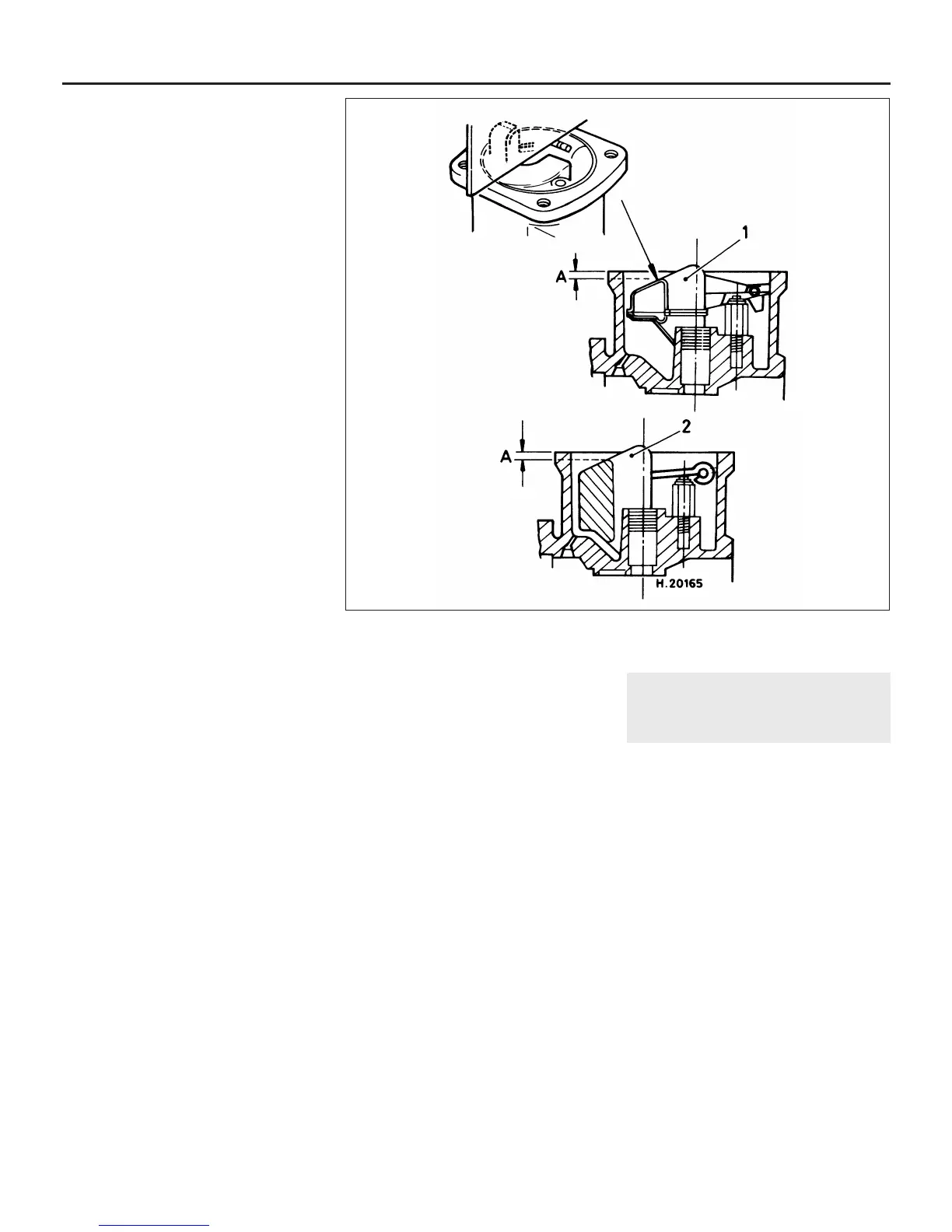
47 To check the float level adjustment, hold
the carburettor inverted with the float keeping
the needle valve shut. Using a straight edge
and feeler blade, check that the centre portion
of the float is 1.0 ± 0.5 mm below the surface
of the float chamber face (see illustration). If
not, bend the tab which contacts the needle
valve as necessary.
48 Fit the float chamber cover in its original
position, together with a new sealing ring.
Tighten the screws in diagonal sequence.
49 Insert the spring, needle, and guide into
the piston with the guide etch marks facing
the dashpot transfer holes, and with the
bottom face of the guide flush with the bottom
face of the piston (see illustration 13.36).
50 Insert and tighten the guide retaining grub
screw.
51 Lower the piston and needle assembly
into the main body, at the same time engaging
the slot with the piston key.
52 Locate the spring over the piston rod.
53 Hold the dashpot directly over the piston
with its location mark aligned with the mark on
the body, then lower it over the spring and
piston rod. It is important not to tension the
spring by twisting the dashpot.
54 Insert and tighten the dashpot retaining
screws. Lift the piston with a finger, then
release it and check that it returns to the
venturi bridge without any assistance. If not, it
may be necessary to loosen the retaining
screws and slightly reposition the dashpot.
55 Hold the piston fully up, then fit the clip to
the top of the piston rod.
56 Pour the specified type of oil into the top
of the dashpot until the level is 13.0 mm
above the top of the hollow piston rod. Refit
and tighten the piston damper.
SU HIF38 carburettor
57 At the time of writing, no specific
information on the HIF38 carburettor fitted to
the 1992-on 1275 cc models was available.
However the carburettor is really only a
slightly smaller version of HIF44 (38 mm bore
instead of 44 mm) it is otherwise identical.
Therefore, the carburettor can be overhauled
using the information given above, noting that
it will be necessary to refer to a Rover dealer
for correct float height measurements; those
given in paragraph 47 are only applicable to
the HIF44 carburettor.
15 Carburettor (SU HS2 and
HS4) - idle speed and mixture
adjustment
3
Preliminary information
1 Three adjustments are possible on the SU
carburettor. These are the engine idling
speed, fast idling speed and mixture strength.
The mixture strength is particularly important
as the initial setting, carried out with the
engine idling, determines the mixture strength
throughout the entire engine speed range. A
good indication as to whether carburettor
adjustment is necessary can be gained by
checking the colour of the exhaust tailpipe
and listening to the note of the exhaust at
idling speed. If the tailpipe is black and the
engine appears to be hunting, it is quite likely
that the mixture is too rich. If the exhaust is
light grey or white in appearance,
accompanied by a rhythmic puffing sound,
this would indicate a weak mixture. Ideally,
the exhaust should be a medium grey colour
and emit a steady even drone. The colour of
the spark plugs will also give a good
indication as to the mixture strength and
general engine condition (see Chapter 1).
These checks should only be carried out after
4A•16 Fuel system - carburettor engines
14.47 SU HIF carburettor float level adjustment “A”
1 Type 1 float 2 Type 2 float A = 1.0 ± 0.5 mm
 Loading...