a good run of about 5 to 10 miles. Idling in city
traffic and stop/start motoring is bound to
cause excessively dark exhaust pipe and
spark plug deposits.
2 Before carrying out any adjustments to the
carburettor, ensure that the ignition system is
in good condition, that the spark plugs,
contact breaker points and ignition timing
settings are correct, and that the engine is at
normal operating temperature. Check also
that the carburettor dashpot oil damper is
topped up to the correct level with the
specified grade of oil.
3 Depending on year of manufacture either a
sealed or non-sealed carburettor may be
fitted. Early models are equipped with the
non-sealed type, identified by the throttle and
fast idle adjusting screws which are clearly
visible and retained by a tension spring or
locknut. On the sealed carburettors the
throttle adjusting screw is located in a
recessed hole in the carburettor body and
may be covered by a small circular metal cap.
4 Carburettor adjustment is carried out as
follows, according to type.
Adjustment
Single carburettor installations - non-
sealed type
5 Remove the air cleaner assembly as
described in Section 2.
6 Connect a tachometer to the engine (if one
is not already fitted to the car), following the
manufacturer’s instructions. If your ears can
attune to slight changes in engine rpm or to
alterations of the exhaust note, then it is
possible to carry out the adjustments without
the use of a tachometer.
7 Set the engine idling speed by turning the
throttle adjusting screw until the specified
idling speed is obtained (see illustrations).
Note: If the throttle adjusting screw is secured
by a locknut, slacken the locknut before
turning the adjusting screw and leave it
slackened until all the carburettor adjustments
have been completed.
8 To check the mixture strength, press the
piston lifting pin on the side of the carburettor
upwards, against light spring resistance, until
it comes into contact with the piston. Now
press it up a further 1.0 mm and listen to the
engine speed. This will indicate one of the
following:
a) If the speed of the engine increases
appreciably, the mixture is too rich.
b) If the engine speed immediately
decreases or the engine stalls, the mixture
is too weak.
c) If the engine speed remains constant or
increases very slightly, the mixture is
correct.
9 To enrich the mixture, rotate the jet
adjusting nut located at the base of the
carburettor in a clockwise direction as viewed
from above, ie downward. To weaken the
mixture, rotate the jet adjusting nut anti-
clockwise as viewed from above, ie upward,
while at the same time pushing the jet
assembly upwards against the nut. When
altering the mixture strength, only turn the nut
one flat at a time and check the mixture with
the lifting pin each time.
10 It is quite likely that there will be a slight
increase or decrease in engine rpm, after the
mixture adjustment has been made. This
should be corrected by turning the throttle
adjusting screw, until the specified idling
speed is again obtained.
11 With the engine idling at the specified
speed and the mixture correctly adjusted,
check the fast idle adjustment as follows.
12 Rotate the choke linkage on the side of
the carburettor, to the point where the linkage
just starts to lower the jet. Hold the linkage in
this position and rotate the fast idle
adjustment screw, until the specified engine
fast idle speed is obtained.
13 When all adjustments are complete,
disconnect the tachometer, refit the air
cleaner and road test the car, carrying out any
small adjustments that may be necessary, on
the road.
Fuel system - carburettor engines 4A•17
4A
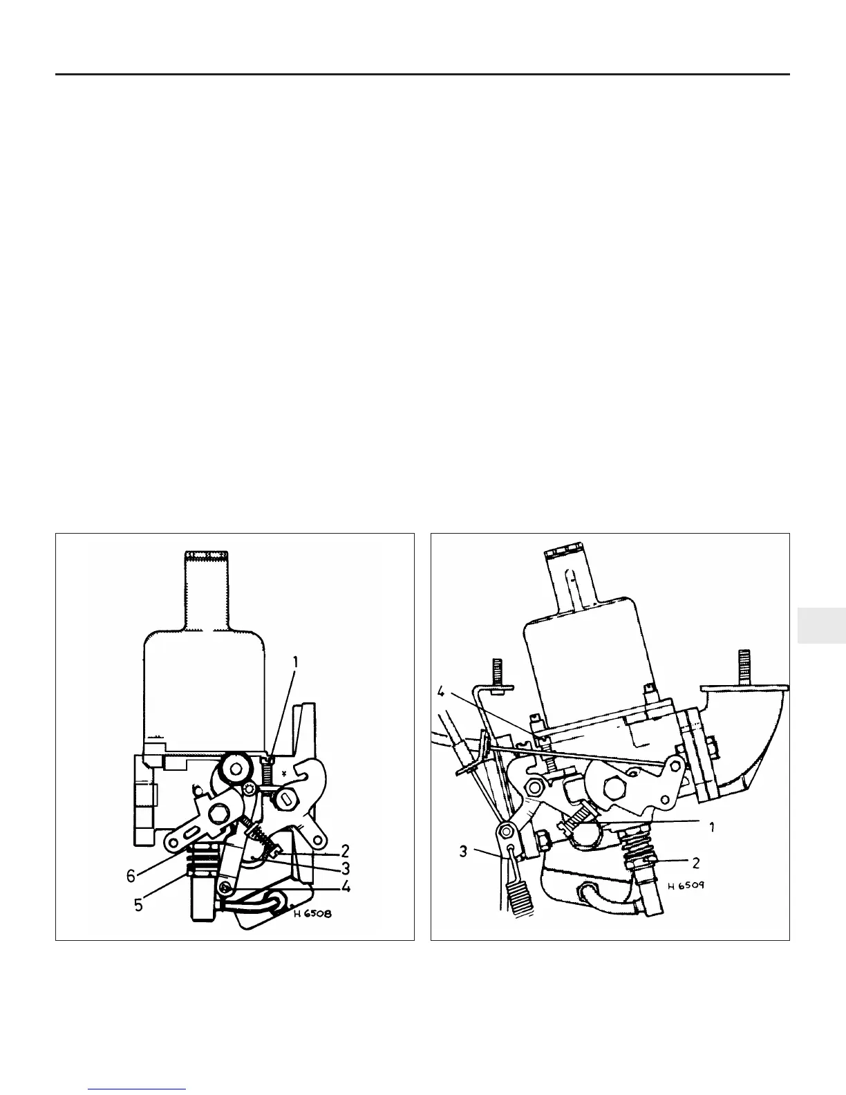
15.7a Carburettor adjustment points – SU HS2
1 Throttle adjusting screw
2 Fast idle adjusting screw
3 Float chamber bolt
4 Jet link securing screw
5 Jet adjusting nut
6 Jet locknut
1 Fast idle adjusting screw
2 Jet adjusting nut
3 Governor control rod
(automatic transmission)
4 Throttle adjusting screw
15.7b Carburettor adjustment points – SU HS4
 Loading...