Single carburettor installations -
sealed type without open-loop
catalytic converter
14 Remove the air cleaner assembly as
described in Section 2.
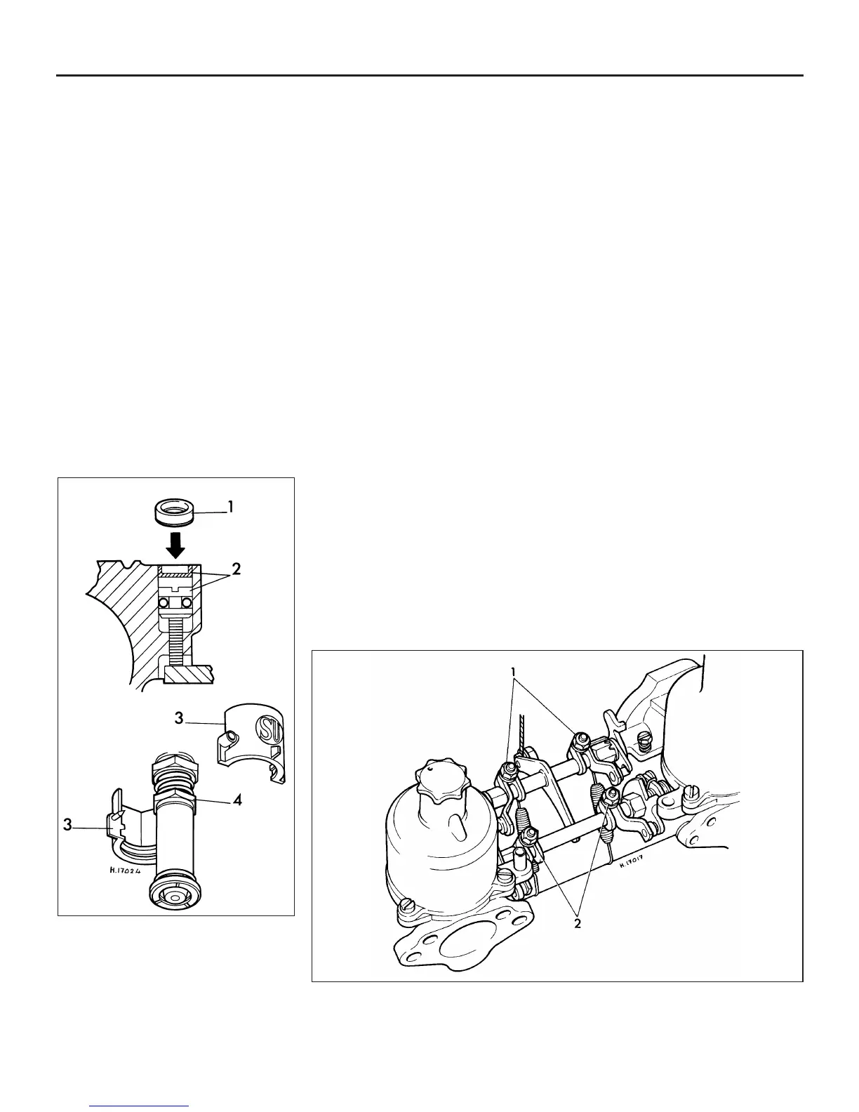
15 If the tamperproof seals are still in position
over the throttle adjusting screw and mixture
adjusting nut, remove and discard them (see
illustration). The seal over the throttle
adjusting screw can be hooked out of the
recess using a small screwdriver. The seal on
the jet adjusting nut can be removed by
prising it open with a screwdriver and then
lifting away the two halves.
16 Connect a tachometer to the engine (if
one is not already fitted to the car), following
the manufacturer’s instructions. If your ears
can attune to slight changes in engine rpm or
to alterations of the exhaust note, then it is
possible to carry out the adjustments without
the use of a tachometer.
17 Set the engine idling speed, by turning the
throttle adjusting screw until the specified
idling speed is obtained.
18 Turn the jet adjusting nut located at the
base of the carburettor in a clockwise or anti-
clockwise direction, one flat at a time, until the
fastest possible engine speed consistent with
even running is obtained. Turning the nut
clockwise as viewed from above, ie
downward, enriches the mixture. Turning the
nut anti-clockwise as viewed from above, ie
upward, weakens the mixture.
19 It is quite likely that there will be a slight
increase or decrease in engine rpm after the
mixture adjustment has been made. This
should be corrected by turning the throttle
adjusting screw until the specified idling
speed is again obtained.
20 The remainder of the adjustment
procedure is the same as described
previously for non-sealed carburettors in
paragraphs 11 to 13.
Single carburettor installations -
sealed type with open-loop catalytic
converter
21 On 1992-on 998 cc models equipped with
an open-loop catalytic converter, the idle
speed and mixture adjustments can be
carried out as described previously in
paragraphs 14 to 20, but using an exhaust
gas analyser to check the CO content of the
exhaust gas.
22 The gas analyser should be used in
accordance with the maker’s instructions and
connected to the take-off point at the top of
the exhaust system front pipe. To do this, it
will first be necessary to jack up the front of
the car and support it on axle stands.
23 Unscrew the threaded plug from the front
pipe, and screw the gas sampling pipe
adapter into the threaded hole; the adapter
can be obtained from a Rover dealer. The gas
analyser should then be connected to the end
of the sampling pipe.
24 On completion, unscrew the sampling
pipe, then refit the threaded plug and tighten it
securely.
Twin carburettor installations
25 Before adjusting the mixture strength on
models fitted with twin carburettors, it is
necessary to ensure that the volume of air
passing through each carburettor is the same.
This is done as follows.
26 Remove the air cleaner assembly as
described in Section 2.
27 Slacken the two clamp bolts on the
throttle spindle operating arms and the two
clamp bolts on the choke spindle operating
arms (see illustration).
28 Start the engine without depressing the
accelerator and allow it to idle.
29 Using a proprietary balancing meter, in
accordance with the manufacturer’s
instructions, balance the carburettors by
altering the throttle adjusting screws until the
airflow through both carburettors is the same.
30 Alternatively, use a length of small bore
tubing, such as heater hose, approximately
457 mm long, to compare the intensity of the
inlet hiss on both carburettors. Turn the
throttle adjusting screws until the hiss sounds
the same in both carburettors. It should be
noted that this method is not really
recommended, as it tends to be somewhat
less accurate, and certainly more difficult,
than using a balancing meter.
31 When the two carburettors are balanced,
bring the engine idling speed back to the
specified rpm by turning both throttle
adjusting screws by equal amounts.
32 Now tighten the two clamp bolts, on the
throttle spindle operating arms, making sure
4A•18 Fuel system - carburettor engines
15.15 The tamperproof caps fitted to the
later type sealed carburettors
1 Throttle adjusting screw cap
2 Throttle adjusting screw showing
cap in position
3 Jet adjusting nut seals
4 Jet adjusting nut
15.27 Throttle and choke linkage – Cooper S models
1 Throttle spindle operating arms 2 Choke spindle operating arms
 Loading...