that a slight clearance exists between the peg
and the lower edge of the fork. Ensure also
that the arms are positioned in such a way
that both carburettor throttles open at the
same time, when the accelerator pedal is
depressed. If necessary, reposition one of the
arms slightly to achieve this condition.
33 Now adjust the mixture strength for each
carburettor using the procedure described in
paragraphs 8 and 9.
34 If the idling speed requires adjustment
after setting the mixture, turn both throttle
adjusting screws by an equal amount in the
desired direction.
35 The choke spindle operating arms can
now be positioned and tightened using the
method described previously for the throttle
operating arms.
36 Finally, adjust the fast idle speed as
follows.
37 Pull out the choke control knob or operate
the linkage by hand, until the linkage just
starts to lower the jets. Hold the linkage in this
position and turn the fast idle adjusting
screws, on both carburettors, until the
specified fast idle speed is obtained and both
carburettors are passing the same volume of
air.
38 Adjustment of the carburettors is now
complete. Refit the air cleaner and carry out a
thorough road test.
16 Carburettor (SU HIF44 and
HIF38) - idle speed and
mixture adjustment
3
Note: A tachometer and accurately calibrated
exhaust gas analyser (CO meter) will be
required for the following adjustments. If these
instruments are not available, the car should
be taken to a Rover dealer for the work to be
carried out.
Preliminary information
1 Refer to Section 15, paragraphs 1 and 2,
then check the following items:
a) The crankcase ventilation hoses are
secure and in good condition (Chapter
4C).
b) The choke cable is correctly adjusted
(Section 5).
c) The accelerator cable is correctly
adjusted (Section 3).
d) The fast idle screw is correctly adjusted,
so that there is clearance between the
screw and the cam with the choke control
off.
2 Run the engine to normal operating
temperature. Driving the car on the road for
approximately 4 miles will achieve this.
3 The adjustments should be completed
within two minutes of the engine reaching
normal temperature, before the electric
cooling fan operates. If the adjustments are
not completed within the two minutes or if the
cooling fan operates, wait for the fan to switch
off, then increase the engine speed to 2000
rpm for approximately 30 seconds. The
adjustments can then be resumed.
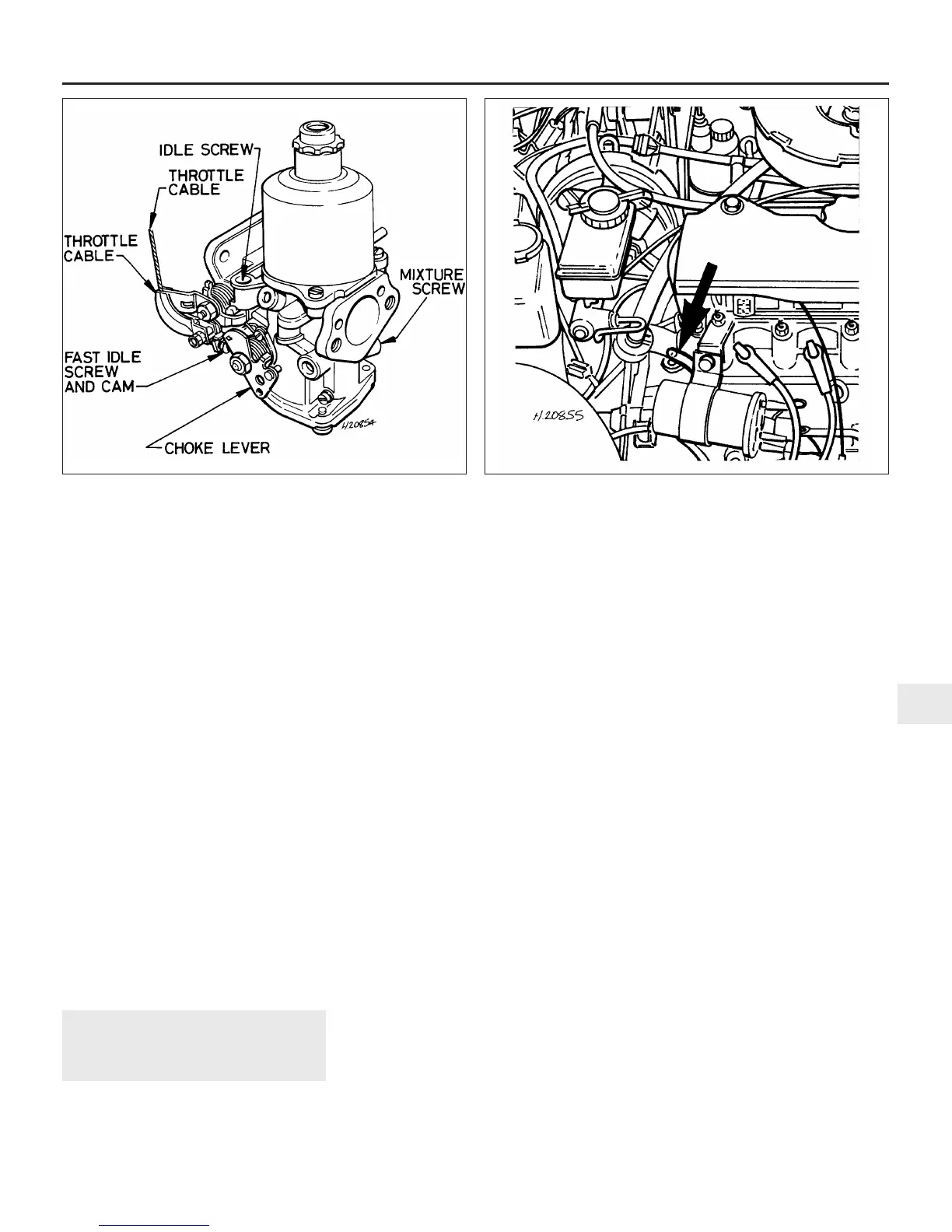
4 To adjust the mixture setting on Cooper
models, it will be necessary to unscrew the
plug from the gas sampling pipe which is
situated on the right-hand end of the cylinder
head, and connect an exhaust gas analyser to
the end of the pipe (see illustration). On all
other models, the exhaust gas analyser
should be connected to the take-off point on
the exhaust system front pipe, using a gas
sampling pipe adapter (which can be obtained
from a Rover dealer). To fit the pipe, jack up
the front of the car and support it on axle
stands (see “Jacking and vehicle support”).
Unscrew the threaded plug from the exhaust
system front pipe, screw the gas sampling
pipe into the threaded hole, and connect the
exhaust gas analyser to the end of the
sampling pipe.
Adjustment
Note: If it has been noted that the engine idle
speed has become erratic, and a high CO %
reading is obtained during the following
procedure, it is likely that the carburettor
needle valve is faulty. Rover have produced a
modified needle valve kit to overcome this
problem. Refer to your Rover dealer for further
information.
5 Check that all electrical components are
switched off.
6 Connect a tachometer to the engine in
accordance with the maker’s instructions.
7 Allow the engine to idle, and check that the
idle speed is as given in the Specifications. If
adjustment is necessary, turn the screw
located on the dashpot base as necessary
(see illustration).
8 With the exhaust gas analyser connected
as described in paragraph 4, and the engine
idling, check that the mixture CO % is as
given in the Specifications. If not, turn the
adjustment screw located on the side of the
carburettor body. Turn the screw by small
increments, and allow the reading to stabilise
between adjustments.
9 If necessary, re-adjust the idling speed as
described in paragraph 7.
10 Note that if the CO % is adjusted near the
3.0% upper limit, the efficiency of the catalytic
converter will be reduced. If the CO reading is
Fuel system - carburettor engines 4A•19
4A
16.4 Gas sampling pipe location (arrowed) on 1990-on
Cooper models
16.7 Adjusting location points on the SU HIF
 Loading...