2 Lift up the assembly, then disconnect the
wiring connector from the air temperature
sensor, and the inlet manifold vacuum pipe
from the thermac valve (see illustrations).
3 Remove the air cleaner assembly, and
recover its sealing ring from the throttle body
flange.
Refitting
4 Refitting is the reverse sequence to
removal, ensuring that the sealing ring is
correctly located on the throttle body flange.
3 Air cleaner air temperature
control system - information,
testing and component renewal
1
General information
1 The system is controlled by a thermac
valve/switch mounted in the air cleaner
assembly; when the engine is started from
cold, the switch is closed, to allow inlet
manifold depression to act on the air
temperature control valve in the inlet duct.
This raises a vacuum diaphragm in the valve
assembly, and draws a flap valve across the
cold air inlet, thus allowing only (warmed) air
from the exhaust manifold to enter the air
cleaner.
2 As the temperature of the exhaust-warmed
air in the air cleaner rises, a bi-metallic strip in
the thermac switch deforms, opening the
switch to shut off the depression in the air
temperature control valve assembly. The flap
is lowered gradually across the hot air inlet
until, when the engine is fully warmed-up to
normal operating temperature, only cold air
from the front of the inlet duct is entering the
air cleaner.
Testing
3 To check the system, allow the engine to
cool down completely, then unclip the inlet
duct from the air cleaner body; the flap valve
in the duct should be securely seated across
the hot air inlet. Start the engine; the flap
should immediately rise to close off the cold
air inlet, and should then lower steadily as the
engine warms up, until it is eventually seated
across the hot air inlet again.
4 To check the thermac switch, disconnect
the vacuum pipe from the control valve when
the engine is running, and place a finger over
the pipe end. When the engine is cold, full
inlet manifold vacuum should be present in
the pipe, and when the engine is at normal
operating temperature, there should be no
vacuum in the pipe.
5 To check the air temperature control valve,
unclip the inlet duct from the air cleaner body;
the flap valve should be securely seated
across the hot air inlet. Disconnect the
vacuum pipe, and suck hard at the control
valve stub; the flap should rise to shut off the
cold air inlet.
6 If either component is faulty, it must be
renewed as described below.
Component renewal
Thermac switch
7 Remove the air cleaner assembly as
described in Section 2.
8 Release the lid retaining clips, then remove
the lid and withdraw the air cleaner filter
element.
9 Disconnect the vacuum pipe (see
illustration), then bend up the tags on the
switch clip. Remove the clip, then withdraw
the switch and its seal.
10 Refitting is the reverse sequence to
removal, ensuring that the switch mating
surfaces are clean, and that the switch and
seal are correctly located before fastening the
clip.
Air temperature control valve
11 Disconnect the vacuum pipe from the
valve, then unclip the inlet duct from the air
cleaner and remove it from the engine
compartment.
12 The air temperature control valve can be
renewed only with the complete inlet duct
assembly. If a new inlet duct assembly is
being fitted, undo the three screws securing
the hot air inlet adapter plate to the bottom of
the duct, and transfer the adapter plate to the
new duct (see illustration).
13 Clip the duct into position in the air
cleaner, and reconnect the vacuum pipe.
4 Accelerator cable - removal,
refitting and adjustment
2
Removal
1 Remove the air cleaner assembly as
described in Section 2.
2 Remove the engine management ECU as
described Section 13.
3 Slacken the accelerator cable locknuts, and
free the outer cable from its mounting bracket.
Release the inner cable from the throttle cam.
4 Work back along the outer cable, releasing
it from any relevant retaining clamps and ties,
and from the engine compartment bulkhead.
5 Working from inside the car release the
heater duct from underneath the driver’s side
of the facia panel, to gain access to the upper
end of the accelerator pedal.
Fuel system - fuel injection engines 4B•3
4B
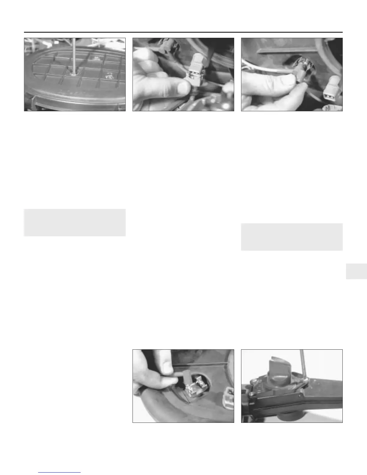
2.1 Undo the three retaining screws . . . 2.2a . . . then lift up the air cleaner
assembly, and disconnect the intake air
temperature sensor wiring connector . . .
2.2b . . . and the thermac valve vacuum
pipe
3.9 Disconnecting the vacuum pipe from
the thermac valve
3.12 Removing the air cleaner intake duct
adapter
 Loading...