6 Remove the accelerator cable retaining clip,
then release the cable from the upper end of
the accelerator pedal. Return to the engine
compartment, and withdraw the cable from
the bulkhead.
Refitting and adjustment
7 Refitting is the reverse sequence to
removal, ensuring that the cable is correctly
routed. Prior to tightening the cable locknuts,
the cable should be adjusted as follows.
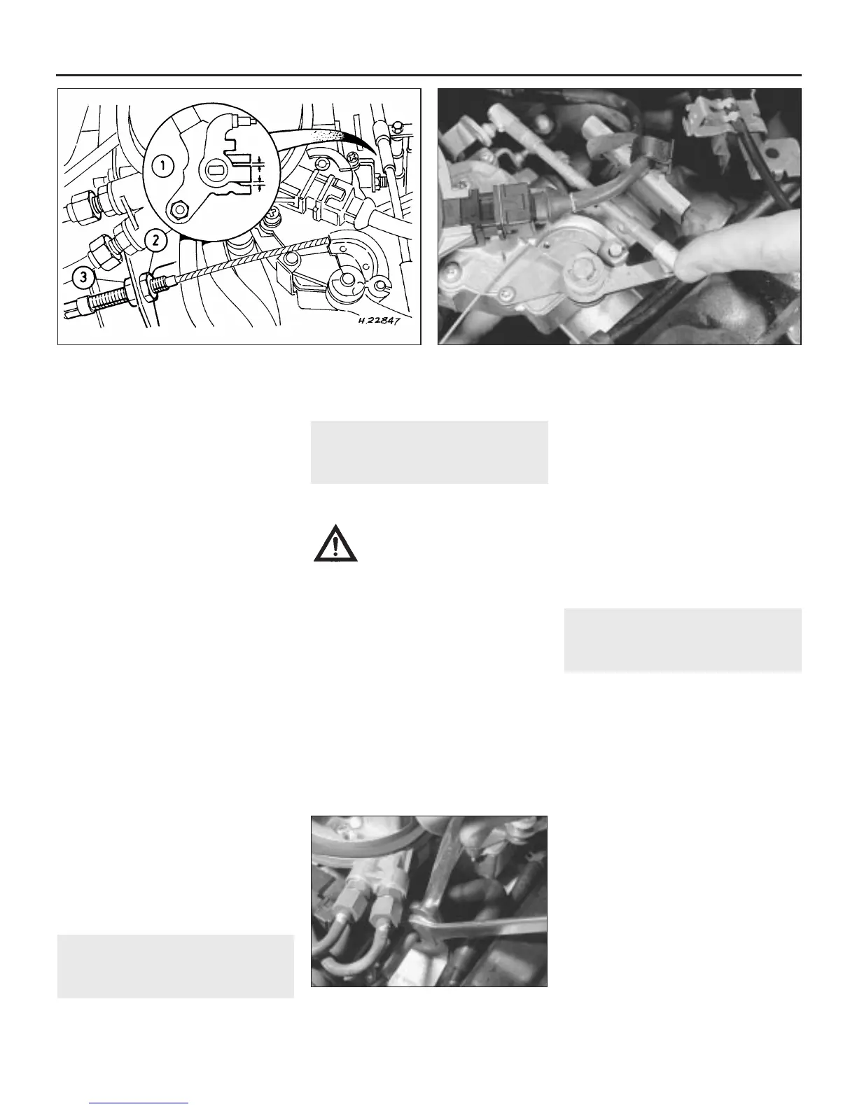
8 With the pedal fully released, position the
locknuts so that there is equal clearance
present on each side of the throttle lever at
the lost motion link and no slack in the cable
(see illustration). Have an assistant fully
depress the pedal, and check that the throttle
cam opens fully, then check that it returns to
the at-rest position when released.
9 To adjust the cable, switch on the ignition
and position the stepper motor by moving the
cam only to open, and fully close the throttle
(see illustration). Note that it is essential for
accurate positioning of the stepper motor that
the accelerator pedal switch contacts remain
closed, so that the ECU recognises the
throttle movement as a command, and
indexes the stepper motor.
10 Slacken the adjuster locknut, then tighten
the adjuster nut until the clearance is equal on
each side of the throttle lever at the lost
motion link, tighten the locknut without
disturbing this setting (see illustration).
Recheck the adjustment, and switch off the
ignition.
5 Accelerator pedal - removal
and refitting
1
Refer to Part A, Section 4.
6 Fuel system -
depressurisation
1
Note: Refer to the warning note in Section 1
before proceeding.
Warning: The following
procedure will merely relieve the
pressure in the fuel system -
remember that fuel will still be
present in the system components, and
take precautions accordingly before
disconnecting any of them.
1 The fuel system referred to in this Section is
defined as the tank mounted fuel pump, the
fuel filter, the fuel injector and the pressure
regulator in the injector housing, and the
metal pipes and flexible hoses of the fuel lines
between these components. All these contain
fuel which will be under pressure while the
engine is running and/or while the ignition is
switched on. The pressure will remain for
some time after the ignition has been
switched off, and must be relieved before any
of these components are disturbed for
servicing work.
2 Disconnect the battery negative lead.
3 Place a suitable container beneath the
relevant connection/union to be
disconnected, and have a large rag ready to
soak up any escaping fuel not being caught
by the container.
4 Loosen the connection or union nut (as
applicable) slowly to avoid a sudden release
of pressure, and position the rag around the
connection to catch any fuel spray which may
be expelled. Once the pressure is released,
disconnect the fuel line, and insert suitable
plugs to minimise fuel loss and prevent the
entry of dirt into the fuel system.
7 Fuel system - pressure check
4
Note: The following procedure is based on the
use of the Rover pressure gauge and adapter
(service tool number 18G1500).
1 Depressurise the fuel system as described
in Section 6, then release the retaining clip
and disconnect the flexible fuel feed hose at
its union to the metal fuel pipe which is
secured to the engine compartment bulkhead,
just behind the throttle body assembly; the
feed pipe is the lower of the two.
2 Connect the gauge into the fuel line
between the hose and pipe, and check that it
is securely retained.
3 Reconnect the battery and start the engine;
the pressure should be steady at the specified
regulated injection pressure. Stop the engine
and watch the gauge; the pressure drop in the
first minute should not exceed 0.7 bars.
4 If the regulated pressure recorded was too
high, the pressure regulator must be renewed;
this means renewing the complete injector
housing assembly.
5 If the pressure first recorded was too low,
or if it falls too quickly, check the system
carefully for leaks. If no leaks are found, first
4B•4 Fuel system - fuel injection engines
4.10 . . . then adjust the locknut and
adjuster nut as described in text
4.8 Accelerator cable adjustment - fuel-injected models
1 Throttle lever-to-lost motion
link clearance should be equal
on each side
2 Adjuster locknut
3 Adjuster nut
4.9 To adjust the accelerator cable, index the stepper motor . . .
 Loading...