each adapter, unscrew the pipe union nuts,
and release the fuel feed and return pipes
from the adapters (see illustration). Plug
each pipe and adapter, to minimise the loss of
fuel and prevent the entry of dirt into the
system.
4 Release the wire retaining clips, and
disconnect the wiring connectors from the
injector housing, the throttle potentiometer
and the stepper motor.
5 Slacken the accelerator cable locknuts, and
free the outer cable from its mounting bracket.
Release the inner cable from the throttle cam.
6 Release the retaining clip(s), and
disconnect the breather and purge valve
hoses from the front of the throttle body (see
illustration).
7 On models with automatic transmission,
disconnect the governor control rod from the
throttle linkage.
8 Slacken and remove the four nuts securing
the throttle body to the inlet manifold, then
remove the throttle body from the car.
Remove the insulating spacer, and examine it
for signs of wear or damage, renewing it if
necessary.
9 If leakage was detected from the feed and
return pipes or their union nuts, check the
sealing surfaces of the nuts and adapters, and
renew the adapter or the pipe assembly as
necessary. If leakage was detected from the
adapters, unscrew each through one turn with
a spanner, then through two turns by hand; if
the adapter is still a tight fit in the housing, the
threads are damaged, and the housing and
adapters must be renewed as a set. If the
threads are sound, fit new sealing washers to
the adapters and refit them, tightening them
to their specified torque wrench setting.
Refitting
10 Refitting is the reverse sequence to
removal, noting the following points:
a) Ensure that the mating surfaces of the
throttle body and inlet manifold are clean,
then fit the insulating spacer.
b) Tighten the throttle body nuts and fuel
pipe union nuts to their specified torque
settings. Note that when tightening the
injector housing fuel pipe union nuts, do
not use an open-ended spanner to retain
the adapters; this will ensure that the
adapters are securely tightened in the
injector housing.
c) On completion, reconnect and adjust the
accelerator cable as described in Section
4.
Injector housing
Note: Refer to the warning note in Section 1
before proceeding.
Removal
11 Carry out the operations described in
paragraphs 1 to 3.
12 Release the wire retaining clip, and
disconnect the wiring connector from the
injector housing (see illustration).
13 Remove the four screws securing the
injector housing to the throttle body (see
illustration), then lift off the injector housing
and remove the gasket.
14 If leakage was detected from the fuel feed
and/or return pipes, perform the checks
described in paragraph 9.
Refitting
15 Refitting is the reverse sequence to
removal, noting the following points:
a) Ensure that the injector and throttle body
mating surfaces are clean, and fit a new
gasket.
b) Apply thread-locking compound (Rover
recommended Loctite Screwlock or
Nutlock) to the threads of the injector
housing screws, then tighten them to the
specified torque.
c) Tighten the fuel pipe union nuts to the
specified torque setting, noting that when
tightening the union nuts, do not use an
open-ended spanner to retain the
adapters; this will ensure that the
adapters are securely tightened in the
housing.
Fuel injector
Note: As a Rover replacement part, the
injector is available only as part of the injector
housing. Note, however, that it is a Bosch-
manufactured component, and can be
obtained separately through Bosch agents.
Refer to the warning note in Section 1 before
proceeding.
Removal
16 Disconnect the battery negative lead.
17 Remove the air cleaner assembly as
described in Section 2.
18 Slacken and remove the injector
connector cap retaining screw, and lift off the
connector cap (see illustration). As the screw
is slackened, place a clean rag over the cap to
catch any fuel spray which may be released.
The injector can then be lifted out of the
housing.
Refitting
19 Refitting is the reverse sequence to
removal, ensuring that the connector cap
makes good contact with the injector pins.
Fuel pressure regulator
20 The fuel pressure regulator is available
only as part of the injector housing assembly.
Refer to paragraphs 11 to 15 for details on
removal and refitting.
4B•6 Fuel system - fuel injection engines
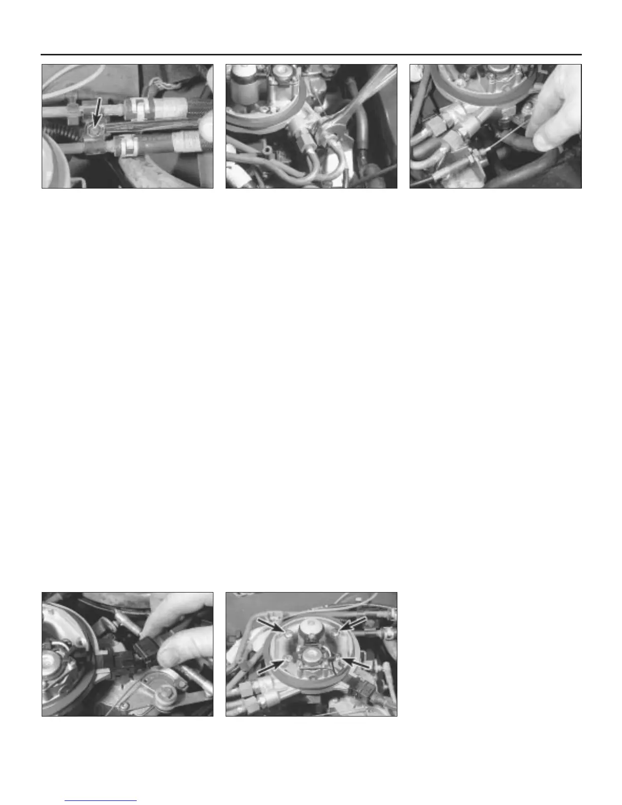
13.2 Undo the retaining bolt (arrowed) and
remove the fuel pipe retaining clip
13.3 Retain the adapters with an open-
ended spanner whilst slackening the fuel
pipe union nuts
13.6 Disconnect the breather and purge
valve hoses from the front of the throttle
body assembly
13.12 Disconnecting the injector housing
wiring connector
13.13 Injector housing retaining screws
(arrowed)
 Loading...