Stepper motor
Removal
21 Remove the injector housing as described
in paragraphs 11 to 14.
22 Release the retaining clip, and disconnect
the stepper motor wiring connector.
23 Remove the four stepper motor retaining
screws, and remove the stepper motor
assembly from the throttle body. Do not
attempt to dismantle the assembly.
Refitting
24 Refitting is the reverse sequence to
removal, ensuring that the throttle body and
motor mating surfaces are clean. On
completion, adjust the accelerator cable as
described in Section 4, to ensure that the
stepper motor is correctly indexed.
Throttle potentiometer
Removal
25 Although not strictly necessary, access is
greatly improved if the air cleaner assembly is
first removed, as described in Section 2.
26 Disconnect the battery negative lead.
27 Release the wire retaining clip, and
disconnect the potentiometer wiring
connector.
28 Remove the two screws, and remove the
potentiometer from the throttle body, noting
how its tongue engages with the throttle disc
spindle lever. Withdraw the spacer if required.
Refitting
29 Refitting is the reverse sequence to
removal, noting the following points:
a) Carefully clean the mating surfaces of the
throttle body, the spacer and the
potentiometer, then refit the spacer.
b) Refit the potentiometer so that its tongue
engages FORWARD of (ie “inside”) the
throttle disc spindle lever, then rotate the
throttle cam to check the action of the
lever and tongue.
c) Securely tighten the potentiometer
screws, then recheck the potentiometer
operation before reconnecting the wiring
connector.
Engine management ECU
Removal
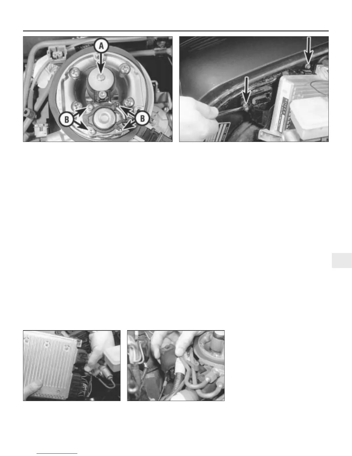
30 Disconnect the battery negative lead, and
undo the two bolts securing the ECU
mounting bracket to the right-hand wing
valance (see illustration).
31 Withdraw the ECU from the engine
compartment, disconnecting its wiring
connectors and the manifold absolute
pressure sensor vacuum hose as they
become accessible (see illustration).
32 If necessary, undo the three screws and
separate the ECU from its mounting bracket.
Refitting
33 Refitting is the reverse sequence to
removal, ensuring that the wiring connectors
and vacuum hose are securely reconnected.
Due to the nature of the ECU, if a new or
different ECU has been fitted, it may take a
short while for full idle control to be restored.
Manifold absolute pressure
(MAP) sensor
34 This is part of the ECU, and is removed
and refitted as described in the previous sub-
section.
35 The sensor’s vacuum hose runs from the
inlet manifold to the ECU via a fuel (vapour)
trap mounted on the engine compartment
bulkhead.
36 To remove the fuel trap, first remove the air
cleaner assembly as described in Section 2.
Release the fuel trap from its retaining clip,
then disconnect the two vacuum hoses, noting
their correct fitted positions, and remove it
from the engine compartment (see
illustration).
37 On refitting, ensure that the vacuum
hoses are reconnected to their original unions;
the hoses are colour-coded to ensure correct
reconnection.
Inlet air temperature sensor
Removal
38 Disconnect the battery negative lead.
39 Remove the air cleaner assembly as
described in Section 2.
40 Unscrew the sensor, and remove it from
the base of the air cleaner housing (see
illustration).
Fuel system - fuel injection engines 4B•7
4B
13.31 . . . then withdraw the ECU and
disconnect the vacuum hose and wiring
connectors
13.36 Removing the manifold absolute
pressure (MAP) sensor fuel
13.18 Injector cap retaining screw “A” and fuel pressure regulator
retaining screws “B”
13.30 Undo the ECU mounting bracket-to-wing valance retaining
bolts (arrowed) . . .
 Loading...