Refitting
41 Refitting is the reverse sequence to
removal. Tighten the sensor to the specified
torque wrench setting.
Coolant temperature sensor -
removal and refitting
Removal
42 The coolant temperature sensor is fitted
to the underside of the inlet manifold, and
access to the sensor is strictly limited.
Therefore, to remove the sensor, it will first be
necessary to remove the inlet manifold as
described in Section 15. The sensor can be
unscrewed and removed from the manifold.
Refitting
43 Wipe clean the threads of the switch and
inlet manifold. If a sealing washer is fitted,
apply a smear of sealant to the switch
threads.
44 Refit the switch to the manifold, and
tighten it securely. Refit the manifold as
described in Section 15.
Accelerator pedal switch
Removal
45 Working from inside the car, release the
heater duct from underneath the driver’s side
of the facia panel, and position it clear of the
accelerator pedal.
46 Using a suitable pair of pliers, unhook the
accelerator pedal return spring from the
pedal.
47 Release the switch wiring connector from
its retaining clip, and disconnect it (see
illustration).
48 Slacken and remove the accelerator pedal
switch mounting bracket retaining bolt, and
remove the switch and bracket assembly from
the car (see illustration).
49 Prise off the C-clip, and remove the
switch from the mounting bracket, noting the
wave washer which is fitted between the
switch and bracket.
Refitting
50 Refitting is the reverse sequence to
removal.
Fuel cut-off inertia switch
51 The fuel cut-off inertia switch is mounted
onto the left-hand side of the engine
compartment bulkhead (see illustration). If the
switch has tripped, it can be reset by pressing
in the button situated at the top of the switch.
Removal
52 Slacken and remove the two screws
securing the cut-off switch to the bulkhead,
then disconnect the wiring connector and
remove the switch.
Refitting
53 Reconnect the wiring connector, then refit
the switch to the bulkhead and tighten its
retaining screws securely. Reset the switch by
depressing the button on the top of the
switch.
Relay module
54 The relay module contains the four main
relays which control the engine management
system; the starter relay, the fuel pump relay,
4B•8 Fuel system - fuel injection engines
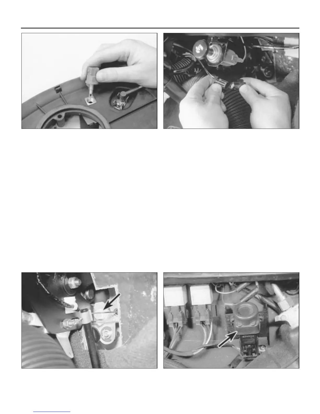
13.48 . . . then undo the retaining bolt (arrowed) and remove the
accelerator pedal switch assembly from the car
13.51 Fuel cut-off inertia switch (arrowed) is mounted onto the
left-hand side of the engine compartment bulkhead
13.40 Removing the intake air temperature sensor from the air
cleaner housing
13.47 Disconnect the wiring connector . . .
 Loading...