the main relay and the manifold PTC heater
relay. If a fault develops in any one of the
system relays, the complete relay module
must be renewed; it is not possible to renew
the separate relays individually.
Removal
55 Slide the relay off its mounting bracket in
the right-hand rear corner of the engine
compartment, then disconnect its wiring
connectors and remove it from the car (see
illustration).
Refitting
56 Refitting is the reverse sequence to
removal.
14 Inlet manifold PTC heater -
general information and
component renewal
3
General information
1 The system incorporates the manifold PTC
(Positive Temperature Coefficient) heater, the
relay and the coolant temperature sensor.
2 When the ignition is switched on and the
engine is cold (coolant below 50ºC), the relay-
energising current is supplied by the engine
management ECU, which then closes the
relay contacts and allows current to flow from
the battery to the heater. This ensures that the
inlet manifold is warm enough, even before
the effect of the coolant heating becomes
apparent, to prevent fuel droplets condensing
in the manifold, thus improving driveability
and reducing exhaust emissions when the
engine is cold.
3 As soon as the engine warms up to
temperatures above 50ºC, the ECU switches
off the supply current, and the relay cuts off
the power supply to the manifold heater.
4 If the engine suddenly develops flat spots
when cold, the system may be faulty.
Component renewal
PTC heater
5 The PTC heater is fitted to the underside of
the inlet manifold, and access to the heater is
strictly limited. Therefore, to remove the
heater, it will first be necessary to remove the
inlet manifold as described in Section 15. With
the manifold on the bench, using circlip pliers,
remove the circlip and withdraw the heater.
Inspect the rubber sealing ring for signs of
damage or deterioration, and renew if
necessary.
6 On refitting, ensure that the heater locating
projection is correctly engaged in the manifold
recess, then secure the switch in position with
its circlip. Refit the manifold to the car as
described in Section 15.
PTC heater relay
7 The manifold PTC heater relay is an integral
part of the relay module, and can be removed
and refitted as described in Section 13.
15 Inlet manifold - removal and
refitting
3
Removal
1 Disconnect the battery negative lead.
2 Remove the bonnet as described in
Chapter 11.
3 Remove the air cleaner assembly as
described in Section 2.
4 Drain the cooling system as described in
Chapter 1.
5 Carry out the operations described in
paragraphs 2 to 7 of Section 13.
6 Undo the union bolt securing the brake
servo vacuum hose to the manifold, and
recover the hose union sealing washers (see
illustration).
7 Slacken the two hose clips, and disconnect
the two coolant hoses from the left-hand side
of the manifold.
8 Disconnect the two vacuum hoses from the
rear of the inlet manifold, noting their correct
fitted positions; the hoses are colour coded
for identification purposes.
9 Slacken and remove the four nuts securing
the inlet manifold to the cylinder head, then
remove the manifold from the engine,
disconnecting the manifold PTC heater and
coolant temperature sensor wiring connectors
as they become accessible. Remove the two
rings from the inlet manifold bore.
Refitting
10 Refitting is the reverse sequence to
removal, noting the following points:
a) Although not strictly necessary, it is also
recommended that the exhaust manifold
is removed, as described in Part C of this
Chapter, so that the manifold gasket can
be renewed before the inlet manifold is
refitted.
b) If leakage was detected from the fuel feed
and/or return pipes, perform the checks
described in Section 13, paragraph 9.
c) Ensure that the manifold and gasket faces
are clean, and that the two locating rings
are in position in the manifold bores
before refitting the manifold.
d) Tighten the manifold retaining nuts to the
specified torque setting.
e) Ensure that all relevant hoses are
reconnected to their original positions,
and are securely held (where necessary)
by the retaining clips.
f) Renew the vacuum servo unit vacuum
hose banjo union sealing washers, and
tighten the union bolt to the specified
torque.
g) Prior to refitting the air cleaner assembly,
adjust the accelerator cable as described
in Section 4.
h) On completion, refill the cooling system
as described in Chapter 1.
Fuel system - fuel injection engines 4B•9
4B
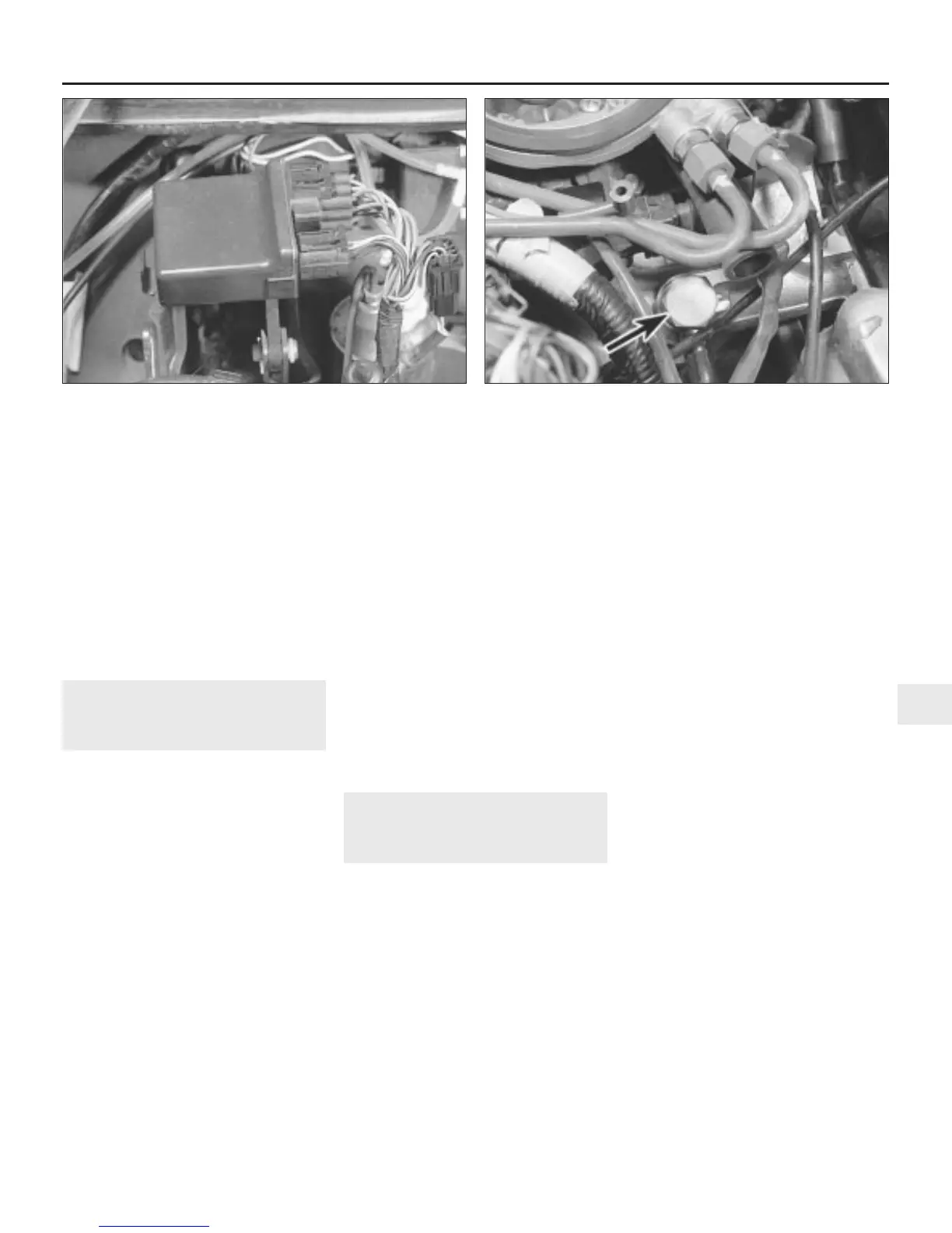
13.55 Relay module is situated on the right-hand side of the
engine compartment
15.6 Inlet manifold brake servo unit vacuum hose union bolt
(arrowed)
 Loading...