1 General information
Exhaust system
The exhaust system fitted to all Mini models
covered by this manual, except Cooper S,
consists of an exhaust manifold and a tubular
steel exhaust system in either single or
multiple sections. A single silencer is fitted to
the rear section of early models; later versions
incorporate an additional intermediate
silencer or catalytic converter. The system
fitted to Cooper S models comprises a three
branch manifold, a front pipe and separate
tailpipe incorporating a silencer. Certain
versions have a second silencer located
beneath the floor pan.
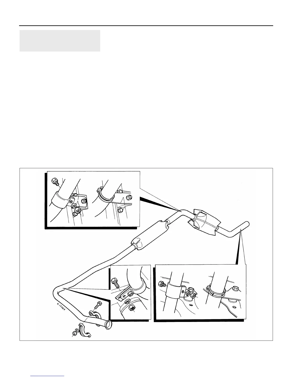
On all models the exhaust system is flexibly
attached to the car by two rubber mountings
on the rear subframe and a bracket at the
base of the transmission.
Emission control systems
Certain early models and all later models
covered by this manual have various features
built into the fuel and exhaust systems to help
minimise harmful emissions. These features
fall broadly into three categories; crankcase
emission control, evaporative emission
control, and exhaust emission control. The
main features of these systems are as follows.
Crankcase emission control
To reduce the emissions of unburned
hydrocarbons from the crankcase into the
atmosphere, a positive crankcase ventilation
system is used whereby the engine is sealed
and the blow-by gasses and oil vapour are
drawn from inside the crankcase, through an
oil separator, into the inlet tract to be burned
by the engine during normal combustion.
Under conditions of high manifold
depression (idling, deceleration) the gasses
will be sucked positively out of the crankcase.
Under conditions of low manifold depression
(acceleration, full-throttle running) the gasses
are forced out of the crankcase by the
(relatively) higher crankcase pressure; if the
engine is worn, the raised crankcase pressure
(due to increased blow-by) will cause some of
the flow to return under all manifold
conditions.
Evaporative emission control
The evaporative emission control system is
used to minimise the escape of unburned
hydrocarbons into the atmosphere.
The fuel tank filler cap is sealed, and a
charcoal canister is mounted underneath the
left-hand wheel arch to collect the petrol
vapours generated in the tank, and on some
models in the carburettor float chamber, when
the car is parked. It stores them until they can
be cleared from the canister into the inlet
tract, to be burned by the engine during
normal combustion.
On early carburettor models, the vapours
were drawn into the inlet tract whenever the
engine was running. On later catalytic
converter equipped carburettor models, a
thermostatic vacuum valve screwed into the
front of the thermostat housing controls the
flow of vapour from the canister to the engine.
To ensure that the engine runs correctly when
it is cold, and to protect the catalytic
converter from the effects of an over-rich
mixture, the thermostatic vacuum valve does
not open until the engine has warmed up to
approximately 70ºC. The valve then allows
inlet manifold vacuum to act upon the purge
valve vacuum diaphragm fitted to the top of
the charcoal canister, which in turn opens the
4C•2 Exhaust and emission control systems
2.2 Typical exhaust system support brackets and mountings
 Loading...