canister and allows the stored vapour into the
inlet tract.
On fuel injection models, the engine
management ECU controls the flow of vapour
from the canister to the engine, via an
electrically-operated purge control valve.
The purge control valve is not opened by
the ECU until the engine has warmed up to
above 70ºC, the engine speed exceeds 1500
rpm and manifold absolute pressure is below
30 kPa; the control valve solenoid is then
modulated on and off to allow the stored
vapour to pass into the inlet tract.
Exhaust emission control -
carburettor models without catalytic
converter
The basis of this system, used on certain
early models, is an air pump which supplies air
under pressure to the cylinder head exhaust
port of each cylinder, via an air injection
manifold. A check valve is incorporated in the
air delivery pipe to prevent a blow-back of
exhaust gases from reaching the pump. Air
from the pump is also supplied to the inlet
manifold via a gulp valve to weaken the rich
fuel/air mixture in the manifold during engine
deceleration and overrun.
The air pump is of the rotary vane type and
is mounted at the front of the cylinder head.
Drive to the pump is by a V-belt from the
water pump pulley. Air enters the pump
through an extraction filter on early models, or
through radial air inlets around the pulley on
later versions. At high engine speeds, excess
air is discharged to atmosphere through a
relief valve.
A diverter valve is incorporated in the air
delivery pipe between the air pump and check
valve. The valve is operated by a cable on early
models, or activated by a vacuum switch on
later types, whenever the choke control is
pulled out. During choke operation, air from the
pump is cut off and diverted to atmosphere.
When the throttle is closed during
deceleration or overrun, a rich fuel/air mixture
is created in the inlet manifold. The gulp valve
fitted between the air pump and manifold is
activated by the depression also created in
the manifold during these conditions, and
opens to admit air from the air pump. The
mixture is thus weakened preventing
excessive exhaust emissions when the
throttle is reopened. A restrictor is also fitted
in the air feed to the gulp valve and prevents
surging when the valve is in operation.
Exhaust emission control -
carburettor models with catalytic
converter
From approximately 1990 onwards certain
models were fitted with an unregulated or
“open-loop” catalytic converter to minimise
exhaust pollution. The converter consists of
an element (or “substrate”) of ceramic
honeycomb coated with a combination of
precious metals (platinum and rhodium) in
such a way as to produce a vast surface area
over which the exhaust gasses must flow; the
assembly being mounted in a stainless-steel
box in the vehicle’s exhaust system. The
precious metals act as catalysts to speed up
the reaction between the pollutants and the
oxygen in the car’s exhaust gasses. HC and
CO being oxidised to form H
2
O and CO
2
.
Exhaust emission control - fuel
injection models
All fuel-injection models are equipped with
a catalytic converter in the exhaust system.
The system, unlike that fitted to carburettor
models, is a “closed-loop” system. The
Lambda sensor in the exhaust manifold
provides the engine management ECU with
constant feedback on exhaust gas content,
which enables the ECU to adjust the inlet
fuel/air mixture to keep the converter
operating at maximum efficiency.
The Lambda sensor has a built-in heating
element, controlled by the ECU through the
Lambda sensor relay to quickly bring the
sensor’s tip to an efficient operating
temperature. The sensor’s top is sensitive to
oxygen, and sends the ECU a varying voltage
depending on the amount of oxygen in the
exhaust gases; if the inlet air/fuel mixture is
too rich, the exhaust gases are low in oxygen,
so the sensor sends a low-voltage signal; the
voltage rises as the mixture weakens and the
amount of oxygen in the exhaust gases rises.
Peak conversion efficiency of all major
pollutants occurs if the inlet air/fuel mixture is
maintained at the chemically-correct ratio for
the complete combustion of petrol - 14.7
parts (by weight) of air to 1 part of fuel (the
“stoichiometric” ratio). The sensor output
voltage alters in a large step at this point, the
ECU using the signal change as a reference
point, correcting the inlet fuel/air mixture
accordingly by altering the fuel injector pulse
width.
2 Exhaust system (models
without catalytic converter) -
removal and refitting
1
All models except Cooper S
Removal
1 Working in the engine compartment,
Exhaust and emission control systems 4C•3
4C
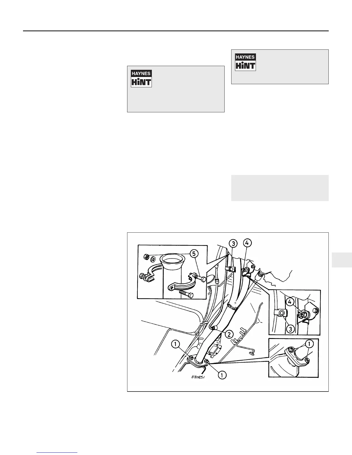
3.2 Exhaust front pipe fitted to models with catalytic converter
1 Catalytic converter flange nuts
2 Gas sampling pipe union nut
3 Gas sampling pipe mounting bolt
4 Front pipe mounting nut
5 Front pipe-to-manifold clamp and
bolts
Position a jack under the
exhaust front pipe and raise
it just sufficiently to hold the
bellmouth tightly against the
manifold flange. This will ensure that
the joint is properly seated as the clamp
is fitted.
Apply liberal amounts of
releasing oil to the exhaust
tailpipe-to-front pipe joint if
it is reluctant to come free,
and allow it time to soak in.
 Loading...