USE ONLY HAYWARD GENUINE REPLACEMENT PARTS
4
Installation
Getting Started
Follow the instructions below before beginning installation:
1. Inspect for concealed damage upon receipt. Advise shipper of damage. File any damage claims with delivering carrier.
2. Spa heater must be installed according to instructions or manufacturer's warranty is void.
3. Your electric spa heater can be located anywhere in an outdoor or indoor location with a minimum clearance of six (6) inches to all combustible con-
struction. Maintain adequate access clearance for servicing heater. Locate your heater in such a way that should the tank or any of its connections leak,
the water will not damage anything. Under no circumstances will we, the manufacturer, be held liable for water damage in connection with your heater.
The heater should be connected in the return line from the filter to the spa. Water shut off valves must not be installed in the piping from the outlet of the
spa heater to the spa. Blocking the return pipe in any fashion can create a hazardous condition.
NOTE: Factors which affect the spa water and, more importantly, the efficiency and operation of your spa heater include:
1. Proper Filtration 3. Disinfection and Oxidation 5. Algae Control
2. Proper Circulation 4. pH Control and Total Alkalinity
pH is the measure of the acidity or alkalinity of water. As shown on the chart below, it is a critical measurement.
We recommend using a four way test kit to obtain the correct:
1. pH (7.2 - 7.8) 3. Total Alkalinity (80 - 120 PPM)
2. Chlorine Residual (1.0 - 5.0 PPM) 4. Calcium Hardness (175-350 PPM depending on spa finish)
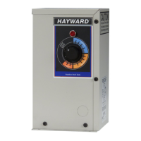
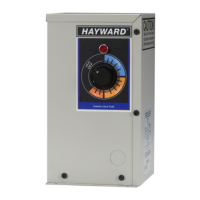
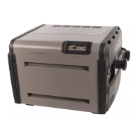
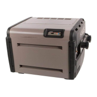
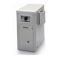
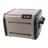
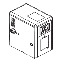
Specifications and Dimensions
* PER NEC LOCAL CODES - APPLY COPPER ONLY
WIRE SIZE APPLIES TO RUNS UP TO 50 FEET
FOR EACH ADDITIONAL 50 FOOT RUN, SELECT WIRE SIZE ONE GAUGE LARGER
Model B.T.U. KW
AMP
RATINGS
240V
Wire
Size*
240V
Ground
Wire
Size*
Breaker
Size*
240V
GHP
20°
Rise
GHP
40°
Rise
Water
Conn.
SHIP
WT.
C-SPA-X1 5.5 18,766 5.5 23 10 10 30 120 56 1½" 14
C-SPA-X1 11 37,532 11 46 6 10 60 225 112 1½" 14
6⁄”
2⁄”
11⁄”
Front
Rear
Side View
6⁄”
6⁄”
1⁄”
Top ViewFront
Rear
0
1 2
3
4 5
6
7 7.4 - 7.6
8
9
10
11
12 13
14
CORROSION ZONE
NEUTRAL
SCALING ZONE
ACID
IDEAL ALKALINE
Heat Components
Destroyed
Heat Components
Destroyed
 Loading...