USE ONLY HAYWARD GENUINE REPLACEMENT PARTS
7
Installation Procedure With Bypass Line
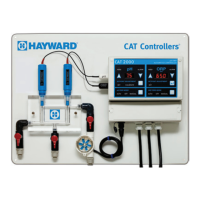
CAT recommends the use of a CAT Flowcell and Rotary Flow Sensor for all recreational water ap-
plications. The CAT Flowcell provides a controlled flow to maximize sensor life, convenient sample
port for manual water tests, integrated mounting of Rotary Flow Sensor, and fast professional
installation with flexible tubing and Tru-seal connectors.
Construction of a bypass line should only be performed by experienced technicians familiar with
the procedures for plumbing with PVC as well as the material used in the existing filtration system.
Refer to the Illustration on the following page for a typical bypass diagram.
1. Turn off heater, chemical feeders, pump, and any other related equipment. Relieve pressure
from filtration system.
2. Select a convenient mounting location for the controller unit which will meet the following
criteria:
A. Facilitates unobstructed bypass line plumbing.
B. Located a minimum of ten feet from pool or spa.
C. GFI protected power source available.
D. Easily accessible to pool or spa operator.
E. Away from corrosive materials and physical hazards.
3. Securely mount the CAT 2000 controller on a vertical wall.
4. Install one “reducing tee” or “saddle tee” fitting each on the incoming suction line to the pump
and the return line upstream from heater as shown in the illustration on the following page.
5. Install ball valves on bypass inlet and effluent immediately adjacent to tee fittings.
6. Install in-line filter (optional) immediately downstream from bypass inlet valve.
7. Install flow meter (optional) immediately downstream from in-line filter (if applicable) or bypass
inlet valve.
8. Install two tee fittings to accommodate ½” NPT Professional Series pH & ORP sensors as
shown in the illustration on the following page.
9. Install Rotary Flow Sensor in bypass line as shown in the illustration on the following page.
10. Remove pH and ORP sensor storage caps and save for future use.
11. Remove BNC protective covers from left side of controller unit and save for future use. NOTE:
These covers protect the controller unit from electro-static discharge (ESD) and should be
used whenever handling the controller unit.
12. Insert the pH and ORP sensors into the two ½” tee fittings. Teflon tape may be used to seal
threads.
13. Carefully route sensor cables to the controller unit, and connect the sensor cables to the
controller unit as labeled. NOTE: Sensor cables are constructed from a specialized coaxial
material - never cut or splice sensor cables.

 Loading...