5
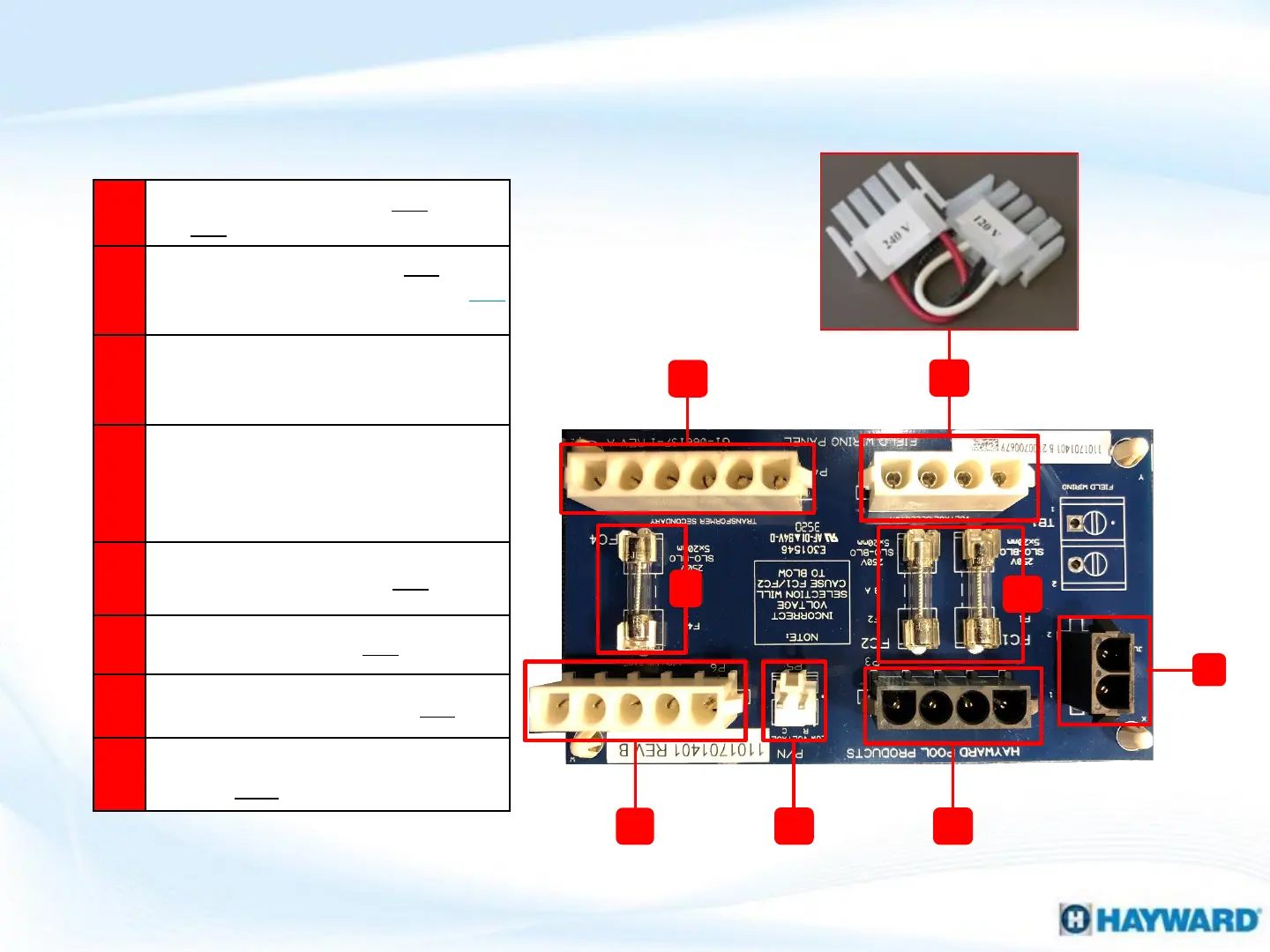
Field Wiring Panel Layout
G
A
C
F
B
D
E
A
Transformer Secondary: 24VAC
120VAC (left) (P4)
B
Voltage Selector 240 OR 120VAC
determined by plug (P2): NOTE: 240
plug factory installed
C
Fuse: 3a protects transformer high
voltage secondary, will fail with blower,
ignitor or ICB failure (FC4)
D
Fuse: 3A protect primary input voltage,
will fail with excessive voltage, improper
wiring, shorted transformer or fuse
board (FC1 & FC2)
E
High Voltage Output: 120VAC (P6)
F
Low Voltage Output: 24VAC (P5)
Transformer Primary: 120/240VAC (P3)
H
Power connection for junction boxes:
 Loading...