EasyManua.ls Logo

Haztec EuroMax 8-8114 Series User Manual

Haztec EuroMax 8-8114 Series
8 pages
To Next Page IconTo Next Page
Page #1 background imageLoading...
Page #1 background image
Haztec International Ltd ∙ Moorfield Road ∙ Leeds ∙ LS19 7BN ∙ UK
T: +44(0)113 202 9115 ∙ info@haztec.uk www.haztec.uk
8-8114-X EuroMax
Siren PA Amplifier
M352.1.0 - 1 - November 2021
Thank you for purchasing this Haztec product. Before proceeding with installation, it is essential
to read and understand this instruction booklet.
Failure to observe the following may result in damage to the system and void any
warranty
Amplifiers can become very hot in use. Please ensure they are mounted such that they
will not cause any damage to surroundings or harm to personnel
Isolate power prior to installation
Check for correct voltage and polarity
Ensure loudspeaker has correct impedance and power capacity
Basic Operating Specifications:
Maximum current draw:
12A @ 12VDC / 6A @ 24VDC
Standby current:
<1mA (+2mA when interlock input activated) 12VDC
<1.5mA (+5mA when interlock input activated) 24VDC
Switched outputs:
2 x 10A relay contacts
Operating temperature range:
-20
O
C to 50
O
C
Output impedance:
11 Ohm
Amplifier distortion:
5%
Frequency range:
300Hz 3Khz
Dimensions (mm):
Amplifier: 164 (L) x 143 (W) x 44.5 (H)
Control Panel: 141 (W) x 44.5 (H) x 27 (D) (+13mm for controls)
Combined: 177 (L) x 156 (W) x 44.5 (H)
100W Siren Amplifier
Dash or remote mount
12 or 24VDC versions
HRT, Interlock & RRB
2 x 10A relay outputs
8-8114 Siren with 8-82104 Controller
Question and Answer IconNeed help?

Do you have a question about the Haztec EuroMax 8-8114 Series and is the answer not in the manual?

Haztec EuroMax 8-8114 Series Specifications

General IconGeneral
BrandHaztec
ModelEuroMax 8-8114 Series
CategoryAmplifier
LanguageEnglish

Summary

Basic Operating Specifications

Connection Instructions

Main Wiring Harness

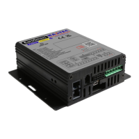
Details the colour coding and connection points for the main wiring harness of the amplifier.

Speaker Connectivity

Explains how to connect the speaker to the amplifier outputs and common wire.

Horn Input

Describes how to connect the vehicle horn switch to change siren tone and mute the horn.

Relay Outputs

Data Logger Output

Details the data logger output, its availability, and when it is present or absent.

Pre-selection of Minimum Volume Setting

Instructions for setting a minimum volume level on 'V' models using controls and switches.

Handset Operation

Night Mode Operation

Toggles night mode on/off. Defaults to off when unit powers up.

Handset Power Off

Turns the handset off with a long press. Cancels siren and lights on second press.

Output #1 Control

Toggles output #1 on/off and controls 'Manual' button operation.

Output #2 Control

Toggles output #2 on and off.

Programmed Tone Switching

Switches outputs #1 & #2 and siren on/off. Starts with 'WAIL' tone.

Wail Tone Operation

Toggles the 'WAIL' siren tone on and off.

Yelp Tone Operation

Toggles the 'YELP' siren tone on and off.

Hi-Lo Tone Operation

Toggles the 'Hi-Lo' siren tone on and off.

Pulsar Tone Operation

Toggles the 'PULSAR' siren tone on and off.

Radio Re-broadcast Mode

Enables radio re-broadcast mode, cancelling any current siren tone.

Auxiliary 2 Function

Controls the Auxiliary 2 function of the siren amplifier.

Manual Mode Operation

Controls 'WAIL' tone or toggles other siren tones based on output #1 status.

Air Horn Operation

Simulates air horn sound when held. Overrides other tones without cancelling them.

Volume Control

Handset thumbwheel controls public address volume; turn clockwise to increase.

Vehicle Horn Function

Operating vehicle horn changes tone as per A-B switch when siren is active.

Operation

Control Panel Tones

Details siren tone activation via rotary switch, including 'Wail' and 'Air Horn'.

Rotary Selector Switch

Selects siren tone (e.g., 'AUX', 'Pulsar') and allows programmable relay outputs.

Relay Output Configuration

Describes the function of Relay Output #1 and Relay Output #2.

Radio Re-broadcast Setup

Connects violet wires for loudspeaker/line output, with trimmer for radio gain adjustment.

A-B Switch Functionality

Toggles current siren tone or reverts to original tone after a set period.

Volume and Mode Controls

Volume (VOL) Control

Controls PA volume and siren volume on variable volume models.

Public Address (PA)

Press-to-talk switch on microphone overrides all and activates the microphone.

Vehicle Horn Tone Change

Operating vehicle horn changes tone as per A-B switch when siren is active.

Variable-volume Tones

Link position on control panel determines fixed or variable volume tones.

Installation Options

Control Panel Attached and Amplifier Mounted on Bracket

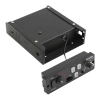
Details fixings and blanking plugs for mounting the control panel and amplifier together.

Control Panel Remote Mount on Top of Surface

Specifies fixings, washers, and blanking plugs for top surface mounting (Bracket Type 'A').

Control Panel Remote Mount in Front of Surface

Details fixings, washers, and blanking plugs for front surface mounting (Bracket Type 'B').

Control Panel Remote Mount onto Existing Surface

Lists fixings and washers for mounting the control panel onto an existing surface.

Supplied Fixings

M6 Fixings and Bracket Type 'A'

Lists M6 set screws, flat washers, and Mounting Bracket Type 'A'.

M6 Fixings and Bracket Type 'B'

Lists M6 set screws, flat washers, and Mounting Bracket Type 'B'.

M4 Fixings

Details M4 set screws, spring washers, and flat washers supplied.

M4 Countersunk Screws

Lists M4 x 12mm countersunk screws provided.

M3 Fixings

Details M3 socket screws, nuts, spring washers, and flat washers.

Blanking Plugs

Lists the blanking plugs supplied with the unit.

Microphone Clip and Screws

Details the microphone clip and associated screws.

Self-Tapping Screws

Lists ST6.2 x 19mm self-tapping screws for mounting bracket to vehicle surface.

Related product manuals