TM 55-1520-228-10
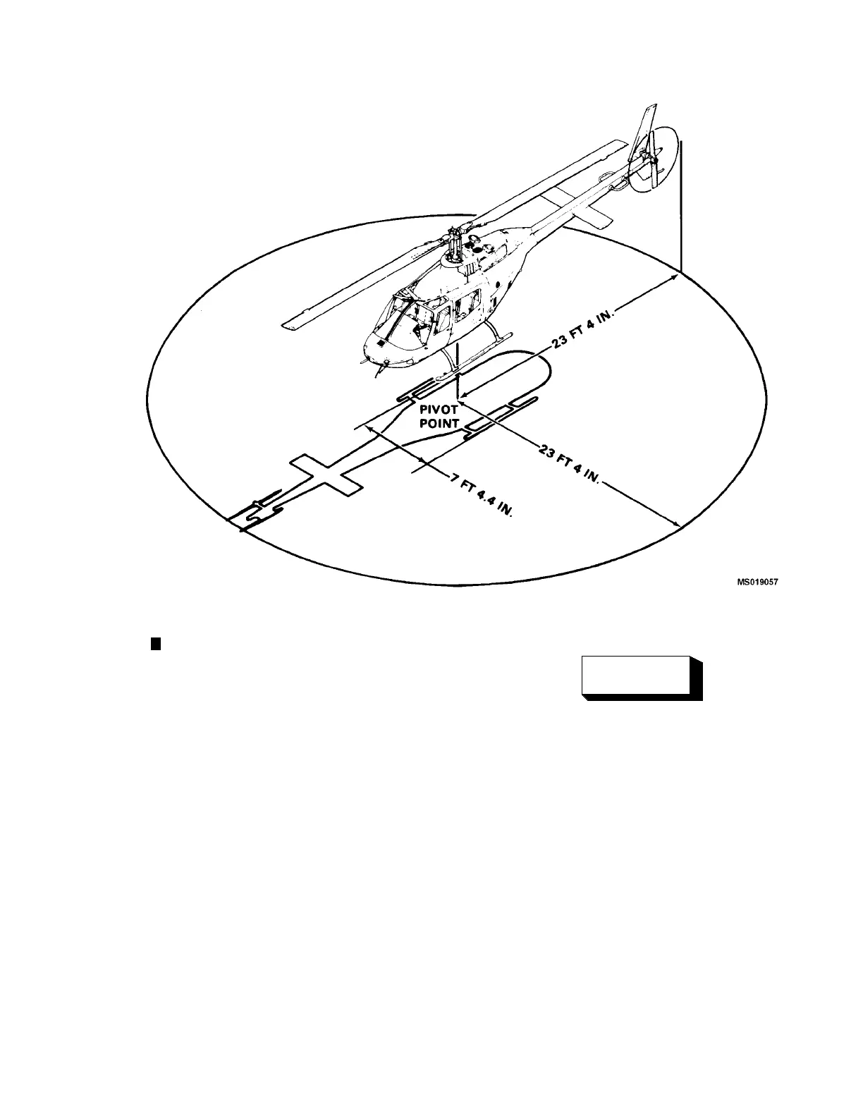
Figure 2-6. Turning Radius and Ground Clearance
c.
A. Floa
tGear.The float landing gear (figure 2-7)
consis
ts of two stream lin ed multi-cell inflatable floa ts,
float support tubes, crosstubes, and necessary fittings
required to equip the helicopter for water landings. A
trian
gular plate is attached to the tail skid for added con-
trollability and protection of the tail rotor in the eve nt of a
tail low water landing. Landing may b e made on smooth
surfa
ces that do not have protrusions that could damage
floats.
d. Tail Skid . A tubular steel tail skid is attached to
the lo
wer section of the vertical fin an d provides protec-
tion for the tail rotor in landings by indicating a tail low
condition.
2-4. COCK PIT AND CABIN DOORS.
WARNING
Inadvertent jettisoning of cockpit doors is pos-
sible if jettison han dle is utilized as a handhold,
or han
d rest during flight.
Four entrance doors are provided for ac cess to the air-
craft interior. The doors are of bonded sheet metal con-
struction with ac rylic plastic windows. Each door may
be jettisoned by means of emergency jettison handle.
All fou r doors are provided with d oo r lock devic es . The
Change 14 2-13
pilot door has a padlock while the other three doors have
loop locking devices (figure 2-8).
 Loading...