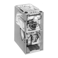
16
in Figure 11, it is recommended that the drip pan extend
at least 12 inches past the top and front of the furnace.
NOTE: Although it is not required to use a drip pan for heat
only applications, state and local codes may require it.
If suspending the furnace from the ceiling, assemble a
support frame (
Figure 12) using slotted iron channel and
full threaded rod. Fasten the frame together with nuts,
washers, and lockwashers. Secure the support frame to the
rafters with lag bolts. The furnace can also be suspended
using steel straps around each end of the furnace. The
straps should be attached to the furnace with sheet metal
screws and to the rafters with bolts.
It is recommended for further reduction of fire hazard
that cement board or sheet metal be placed between the
furnace and the combustible floor and extend 12 inches
beyond the front of the door and top of the furnace.
Special Instructions for GUH92A038A3XE
Furnaces
If installing an GUH92A038A3XE furnace horizontally
(with airflow going from left to right), the pressure switch
will need to be moved to the side of the furnace that is
not facing the ground. See Figure 13. Moving the switch
will make it easier to replace in the future.
1. Shut off any electrical power to the furnace.
2. Label and disconnect the tubing and wires from the
pressure switch (1).
3. Remove two screws (2) securing the pressure switch
(1) to the side of the furnace.
4. Remove two 1/4” black plugs (3) on the opposite side
of the cabinet that the pressure switch will be relocated
to.
5. Position the pressure switch (1) in its new location and
secure it in place using the same screws (2) removed
in step 2
6. Insert the plugs (3) into the holes on the side that the
pressure switch (1) was removed from.
7. Reconnect the tubing and wiring to the pressure switch
(1) being careful that they will not fall into the burner
box.
CAUTION:
8. Check the furnace for proper operation as directed in
Startup and Adjustments section. If the furnace shuts
down during the pre-purge, the switch that measures
pressure in the header needs to be checked for correct
tubing connections.
WARNING:
Figure 13.
PLUGS (X2)
PRESSURE
SWITCHES
SCREWS (X2)
Figure 11.
Flue pipe vented
to outside
J-Trap
Height
3” Min.
Coil Plenum
Wood or
non-combustible
platform
Two-pipe installation shown
Combustion Air
Condensate
Drain Lines
Figure 12.
Lag
Bolt
Nuts (x2)
Washer
and
Lockwasher
Nuts (x2)
Threaded
Rod
 Loading...