Connect the wires from the foil side of the circuit
board. Tug lightly on the wires to be sure they are
soldered.
MAIN
CIRCUIT BOARD1
Page 14
) Connect the blue wire coming from hole J in the main
circuit board to hole J in the display circuit board
(S-1).
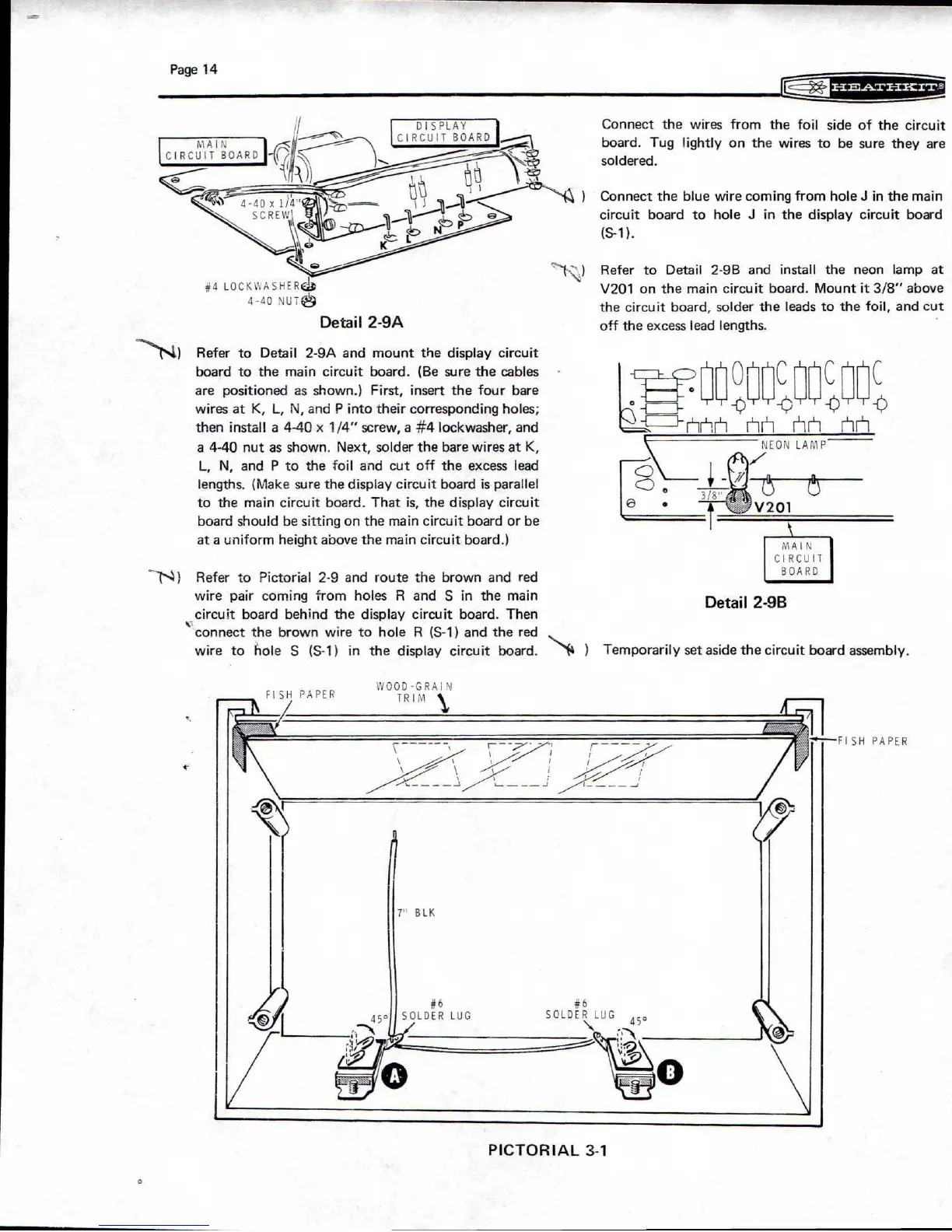
Refer to Detail 2-9B and install the neon lamp at
#4 LOCKWASHERdt
V201 on the main circuit board. Mount it 3/8" above
4-40 NUT
the circuit board, solder the leads to the foil, and cut
Detail 2-9A
off the excess lead lengths.
DISPLAY
CIRCUIT BOARD
WOOD
-
GRAI
TRIM
FISH PAPER
FISH PAPER
r
K
#6
SOLDER LUG
_A
(
#6
SOLDER LUG
_
Refer to Detail 2-9A and mount the display circuit
board to the main circuit board. (Be sure the cables
are positioned as shown.) First, insert the four bare
wires at K, L, N, and P into their corresponding holes;
then install a 4-40 x 1/4" screw, a
#4
lockwasher, and
a 4-40 nut as shown. Next, solder the bare wires at K,
L, N, and P to the toil and cut off the excess lead
lengths. (Make sure the display circuit board is parallel
to the main circuit board. That is, the display circuit
board should be sitting on the main circuit board or be
at a uniform height above the main circuit board.)
--
(`.3) Refer to Pictorial 2-9 and route the brown and red
wire pair coming from holes R and S in the main
circuit board behind the display circuit board. Then
FL1C
NEON LAMP
o
3/8"
e
e
V201
MAIN
CIRCUIT
BOARD
I
Detail 2-9B
connect the brown wire to hole R (S-1) and the red
wire to hole S (S-1) in the display circuit board.
N
*
4
)
Temporarily set aside the circuit board assembly.
PICTORIAL 3-1
 Loading...