Do you have a question about the Heatmiser UH8-RF V2 and is the answer not in the manual?
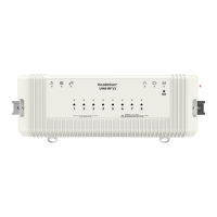
Details the UH8-RF V2 as an 8 Zone central wiring centre for Heatmiser RF thermostats.
Explains zone configuration via toggle switches and output signals for heating/hot water.
Details wall mounting via screws or DIN rail mounting using provided clips.
Covers mains supply and heat/cool enable signalling for the system.
Details wiring for hot water, 8 zones, manifold pump/valve, and their respective connections.
Details zone indicator lights and buttons for manual control and pairing.
The Heatmiser UH8-RF V2 is an 8-zone central wiring center designed for use with Heatmiser RF thermostats, offering comprehensive control over various heating system components. Its primary function is to receive heating signals from paired RF thermostats and translate these into actions for actuators, valves, boilers, and pumps.
The UH8-RF V2 acts as the central hub for your heating system, managing up to eight individual zones. It is capable of controlling any actuator or valve that requires a 230V AC signal to open. For mid-position valves or those needing a closing signal, a changeover relay is required. The unit also provides a volt-free output with changeover contacts to operate a boiler or other heat source, offering both a heat-on and heat-off signal.
Beyond basic zone control, the UH8-RF V2 includes dedicated outputs for hot water and underfloor heating systems. These include pump and valve outputs, typically used to operate a manifold pump or valve in underfloor heating setups. Any output not required for a specific system can simply be ignored.
In scenarios where direct wiring to the heat source is not feasible, the UH8-RF V2 offers a radio link to remotely enable a separate receiver, the RF-Switch, ensuring flexible installation options.
The UH8-RF V2 is designed for ease of configuration and operation. Each channel can be set up as either a radiator zone or an underfloor heating zone using simple toggle switches.
When a thermostat sends a heating signal, the UH8-RF V2 activates the corresponding zone's 230V AC output and simultaneously engages the boiler or other heat source. If the zone is configured for underfloor heating, it will also activate the pump and valve outputs.
For hot water systems, if an enable signal is received from a hot water time clock, only the hot water output becomes active. This is a timed output, typically connected to a cylinder thermostat and then to a valve, but it can also be used for towel rails. The auxiliary switch of the hot water valve would then operate the boiler or heat source.
The unit incorporates several advanced functions to optimize system performance and longevity:
Creepage Protection: This feature addresses the issue of valves and pumps seizing due to infrequent use, especially during warmer periods when heating is not often required. When enabled, the UH8-RF V2 will operate each valve or pump for one minute if it hasn't been activated by a thermostat within the preceding 24 hours. This function does not affect the boiler output.
Pump Delay: Some valves or actuators require more than a minute to fully open. If the boiler and pump activate before the valve is open, it can lead to the boiler locking out. The pump delay function prevents this by delaying the operation of the pump and boiler, allowing sufficient time for actuators and valves to open.
Dew Point Sensor (Cooling Mode Only): In systems with cooling capabilities, the dew point sensor helps prevent condensation. When activated, the sensor sends a signal to the UH8-RF V2 to shut down cooling to the manifold if the dew point is reached. A dedicated indicator light on the unit shows when this function is active.
Engineers Test Switches: A block of 12 DIP switches is provided for installation engineers to test each zone, boiler, pump, and hot water output. These switches allow individual outputs to be manually turned ON for testing purposes. It is crucial that all these switches are returned to the OFF position once installation is complete.
Zone Buttons and Indicators: Each of the eight zones has an associated indicator light and button. The light illuminates when the zone output is active and flashes when the zone is in pairing mode. The buttons allow for manual ON/OFF control of the output with a single press. Holding the button for 5 seconds initiates pairing mode (indicated by a steady flash), and holding it for 15 seconds deletes existing pairings (indicated by a rapid flash).
System Indicators: The UH8-RF V2 features several system indicators:
The UH8-RF V2 supports pairing with various Heatmiser RF thermostats, including Slimline-RF V3, Slimline-RF V1/V2, and NeoAir V2/V2M/V3.
Slimline-RF V3 Pairing:
Slimline-RF V1/V2 Pairing:
NeoAir Pairing (V2/V2M/V3):
The UH8-RF V2 is designed for straightforward installation and maintenance. Test switches are included for engineers to verify functionality. The unit is powered by a 230V AC 50/60Hz mains supply, protected by a 5-amp, 20mm anti-surge fuse. This fuse safeguards all 230V outputs from the board, including zone, pump, and valve outputs.
The device should be fitted as close as possible to the equipment it controls. If it must be placed within a metal enclosure, an extension antenna (EA1) should be fitted and positioned outside the enclosure to ensure proper radio signal reception.
The manual also includes a system configuration table for installers to record details such as zone usage (underfloor or radiator), and zone titles, which aids in future maintenance and troubleshooting.
| Zones | 8 |
|---|---|
| Supply Voltage | 230V AC |
| Max Current | 3A per Zone |
| Wireless Frequency | 868 MHz |
| Model | UH8-RF V2 |
| Power Supply | 230V AC |
| Frequency | 868 MHz |
| Maximum Load | 3A per Zone |
| Compatibility | Heatmiser RF range |
| Type | Underfloor Heating Controller |
| Operating Temperature | 0°C to 40°C |