Do you have a question about the Heatrae Sadia Multipoint 50 and is the answer not in the manual?
The factory-fitted valve must not be removed or restricted. Failure invalidates guarantee and risks danger.
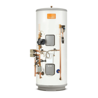
Expansion must be accommodated within the system using the provided Expansion Vessel and Check Valve.
Installation must comply with Building Regulation G3 and be done by a competent installer using supplied parts.
Installation must adhere to relevant Building Regulations and Water Fittings Regulations or Byelaws.
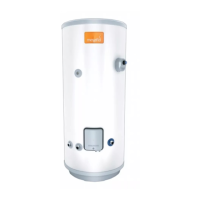
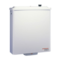
Covers unit location, wall support, space requirements, freeze prevention, and bracket/feet installation.
National Wiring rules may restrict installation in bathrooms.
Plumb valves in sequence as shown, ensuring correct orientation. Support Expansion Vessel with its bracket.
Use 15mm copper tubes with compression fittings. Do not use solder joints. Plumbers paste is prohibited.
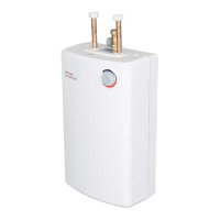
Inlet is BLUE, Outlet is RED. Consider outlet demands. Use WRAS Listed isolating valve. Fit drain cock.
Discharge must be conveyed safely to a visible point without causing danger.
Pipe must terminate visibly, be open to atmosphere, run downwards, and be frost-free.
Pipe size depends on hydraulic resistance (straight pipe equivalent) and BS 6700.
Requires a 300mm vertical section below tundish and a continuous fall.
Discharges must be visible. Be aware of scalding water/steam hazards.
Limit common pipes to 6 systems; common pipe must be one size larger than individual pipes.
Discharge consists of scalding water and steam; may damage certain materials.
Appliance must be earthed, use AC supply only. Disconnect supply before work. Use correct fuse and switch.
Details wire colours for EARTH (Green/Yellow), LIVE (Brown), and NEUTRAL (Blue).
Verify filling, leaks, connections, and relief valves. Ensure electrical supply is safe.
Set temperature via knob. Knob can be locked in mid-range or "hot" position via specific procedures.
Explain heater operation, set temperature, how to isolate supplies, and contact qualified personnel for faults.
Explain maintenance necessity and hand over documentation.
Thermostat range, freeze prevention, indicator light, performance maintenance, and critical user notes on discharge.
Disconnect supplies. Water may be hot. Follow steps for descaling, including shutting off, draining, and removing components.
Includes removing element plate, cleaning, re-assembling with new gasket, and re-commissioning.
Manually operate valves to check water flow and reseating.
Clean the strainer in the pressure reducing valve.
Check and recharge expansion vessel pre-charge pressure (0.35 MPa/3.5 bar) using a tyre pump.
Covers common faults like water not heating, PRV discharge, no water flow, and milky water, with possible causes and actions.
Refer to Rating Label for correct part number. Do not use non-recommended parts.
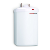
Heater can serve multiple outlets. Consider capacity and number of outlets.
Thermostatic Blending Valve (Accessory Pack U3) recommended for use with this unit.
Five-year guarantee (2 years for element/controls) provided conditions are met.
Not guaranteed against frost damage or excessive scale build-up.
Product is manufactured from recyclable materials. Dispose of at Local Authority Recycling Centre.
Insulation is by means of CFC-free polyurethane foam.
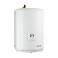
| Capacity | 50 liters |
|---|---|
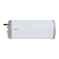
| Installation Type | Wall Mounted |
| Temperature Control | Adjustable Thermostat |
| Wattage | 3 kW |
| Voltage | 230 V |
| Weight | 20 kg |
| Power Supply | Mains Electric |
| Safety Features | Thermal Cut-out |
| Water Pressure | 10 bar |