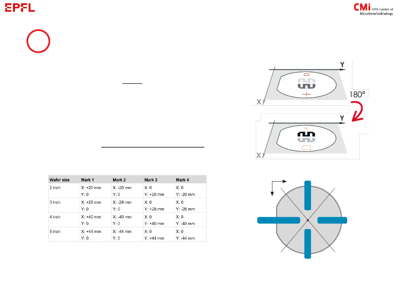
The coordinates on the MLA always refer to the substrate
side that is currently the upper surface (e.g. if an alignment
mark is exposed at the position [X: +20 mm], the alignment
mark will be at position [X: -20 mm] for the backside
alignment.
The alignment marks need to be in a specific area. See blue
zone on the image or layer 65 in the CMi layout template for
exact positions. Example of correct positions :
9