INSTALLATION INSTRUCTIONS R−410A Split System Air Conditioner
14 421 01 1701 00
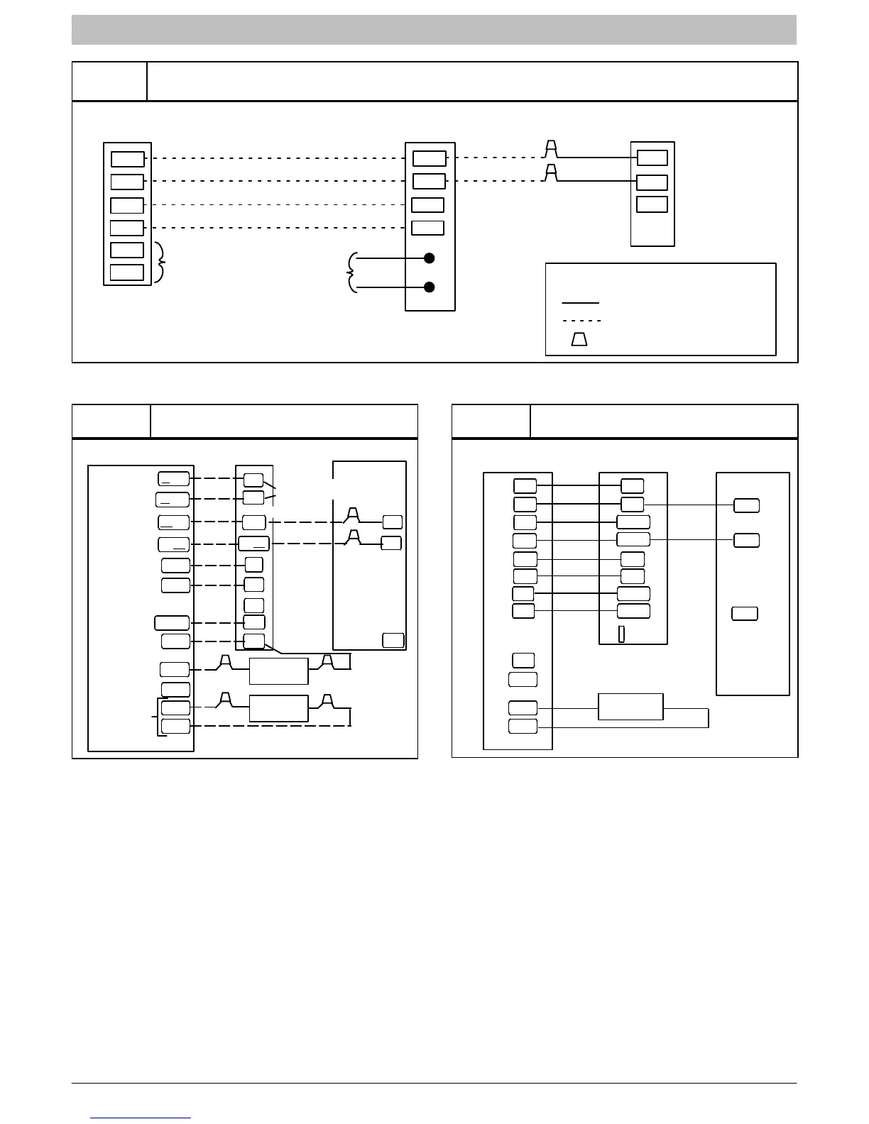
Figure 11
Observer Communicating Wall Control Four−Wire Connection Wiring Diagrams
(See Thermostat Installation Instructions for specific unit combinations)
S1
S2
R
C
DX−
DX+
Optional Remote
Room Sensor
HUM
COM
C
DX−
DX+
Humidifier
Connection
Green
Yellow
White
Red
R
Wall Control
Variable Speed
Furnace/Fan Coil
Outdoor
Green
Yellow
LEGEND
24V FACTORY WIRING
24V FIELD WIRING
FIELD SPLICE CONNECTION
C
DX−
DX+
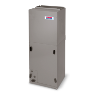
Figure 12
FVM Fan Coil Wiring With
Two−Stage Air Conditioning
Fan Coil
Indoor Control
G
O/W2
R
Y1/W2
W
/W1
Y/Y2
DHUM
C
HUM
B
S1
S2
Heat Stage 2
Heat Stage 1
Cool Stage 1
Fan
24 VAC Hot
Dehumidify
24 VAC Comm
Humidify
RVS Heating
Outdoor
G
R
W2
Y/Y2
C
W1
H
Y2
C
Y1
Two-Stage Air Conditioner
Remove J2 Jumper
For Heat Staging
s
s
Humidifier
(24 VAC)
Outdoor
Sensor
Cool Stage 2
Y1
O
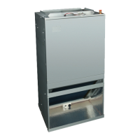
Figure 13
Variable Speed Furnace with
Two−Stage Air Conditioner
Variable Speed
Furnace
ICP Thermostat
G
W2
R
Y1
W1
Y2
C
DHUM
OD
GND
H
Y1
Y2
C
Two-Stage
Heat Pump
G
W2
R
Y1
W/W1
Y/Y2
COM
HUM
L
O/B
OUTDOOR
SENSOR