Do you have a question about the HEIL PGS460115KGP0G PKG-GE and is the answer not in the manual?
General safety precautions, signal words (DANGER, WARNING, CAUTION), and basic hazard types.
Warnings and procedures related to fire, explosion, and gas leaks.
Warnings and procedures concerning electrical shock risks during operation or maintenance.
Procedures for starting and stopping the gas heat operation of the unit.
Step-by-step guide to initiate gas heating operation.
Step-by-step guide to safely turn off gas heating operation.
Critical safety warnings for performing maintenance, including power cutoff and sharp edges.
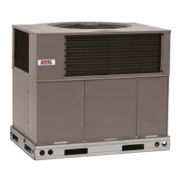
This document is an owner's manual for a 14 SEER Single-Package Air Conditioner and Gas Furnace System, designed to operate with R-410A refrigerant. It covers single-phase units from 2 to 5 nominal tons and three-phase units from 3 to 5 nominal tons, specifically models PGD4, PGS4, and WPG4. The manual provides essential information for owners and installers regarding the safe and efficient operation, maintenance, and troubleshooting of the unit.
The unit is a compact, packaged system that combines both gas heating and electric cooling functionalities. It utilizes R-410A refrigerant for its cooling cycle, which is noted as an environmentally balanced refrigerant. The system is designed to provide comfort by maintaining desired indoor temperatures through either heating or cooling modes. Its operation is primarily controlled by an indoor thermostat, allowing users to set their preferred temperature. The heating section features an automatic direct spark ignition and a power combustion blower for efficient gas heating.
The manual outlines detailed procedures for starting and shutting off both the gas heating and electric cooling functions of the unit.
To initiate gas heating, users must first set the room thermostat to the lowest temperature and the system switch to HEAT. The external manual gas shutoff valve should be closed, and the electrical supply to the unit turned off. After removing the control access panel, the selector switch on the internal gas valve must be moved to the OFF position for 5 minutes, then to the ON position. The control access panel is then replaced, electrical supply turned on, and the external manual gas shutoff valve opened. Finally, the thermostat is set slightly above room temperature to start the unit. The induced-draft combustion air fan will activate, followed by the main gas valve opening and burners igniting within 5 seconds. The manual describes a "Retry Mode" if burners fail to light, and a "lockout" if they don't ignite within 15 minutes of the initial call for heat. Once the unit starts, the thermostat can be set to the desired temperature.
To shut off gas heating, the thermostat temperature selector is set to the lowest temperature, and the system switch to OFF. The external manual shutoff valve is closed, and the electrical power supply to the unit is turned off. The control access panel is removed, the selector switch on the internal gas valve is moved to the OFF position, and the control access panel is replaced. The manual emphasizes that if the unit is being shut down due to a malfunction, the dealer should be contacted. It also provides instructions for situations where overheating occurs or the gas supply fails to shut off, stressing the importance of turning off the external manual gas valve before the electrical supply.
For electric cooling, the thermostat temperature selector is set to the highest temperature, and the system switch to OFF. The external manual shutoff valve should be closed (if not already), and the electrical power supply to the unit turned ON. The system switch is then set to COOL, and the thermostat temperature selector is set slightly below room temperature to start the unit.
To shut off electric cooling, the thermostat temperature selector is set to the highest temperature, and the system switch to OFF. The external manual shutoff valve is closed, and the electrical power supply to the unit is turned off.
The unit's operation is governed by the indoor thermostat, which typically has controls for temperature selection, fan operation, and system mode (COOL, HEAT, OFF). In cooling mode, the unit runs until the indoor temperature reaches the set level, with longer run times on hotter days. Similarly, in gas heat mode, it operates until the room temperature reaches the set level, with longer run times on colder days.
The manual highlights the importance of routine maintenance for ensuring proper functioning and longevity of the unit. While some minor tasks can be handled by the owner, most maintenance should be performed by skilled and experienced personnel, ideally by a dealer who can establish a standard maintenance procedure.
Before any maintenance, it is crucial to turn off the gas supply and all electrical power to the unit and install a lock-out tag. When removing access panels or working inside the unit, users are warned about sharp sheet metal parts and screws, advising the use of safety glasses, protective clothing, and work gloves. The unit area must be kept clear of combustible materials, gasoline, and other flammable liquids and vapors.
Air filters should be checked every 3 to 4 weeks and cleaned or replaced when dirty. Operating the unit without filters can lead to reduced efficiency and damage to the blower motor and/or compressor. Filters can be located in return air filter grilles (wall or ceiling mounted) or in an accessory filter rack inside the unit. The manual provides instructions for replacing filters in accessory filter racks, including removing the filter access panel, pulling out the filter(s), and noting the airflow arrow direction when installing new ones. It also specifies different filter sizes based on unit size and chassis type (small or large chassis) and provides instructions for units with economizers.
Proper airflow for the condenser is vital. A minimum clearance of 48 inches (1219 mm) is required from the top of the unit, and at least 36 inches (914 mm) on the sides, except for the power entry side (42 inches / 1067 mm) and the duct side (12 inches / 305 mm).
Periodic checks of fan wheels, housings, and motor shaft bearings are recommended, with any required service to be performed by the dealer. Users are warned not to insert objects into revolving fan blades.
For dependable and efficient heating, the heat exchanger should be checked by a qualified maintenance person before each heating season and cleaned if necessary. This task requires expertise and specialized equipment.
Cleaning of the coils should only be done by qualified service personnel.
The drain pan and condensate drain line should be checked and cleaned when the cooling coils are serviced.
Compressors are factory-shipped with a normal charge of refrigeration-grade oil and rarely require additional oil.
Electrical controls are complex and require proper instrumentation for checking. Any discrepancies in the operating cycle should prompt a call to the local dealer.
Checking the refrigerant circuit for leaks requires specialized equipment. If inadequate cooling is suspected, the dealer should be contacted.
After any maintenance, all panels must be securely fastened to prevent rain entry and ensure correct unit airflow.
For safe and proper operation, the furnace requires air for combustion and ventilation. Air openings on the furnace and in the installation area must not be blocked. The combustion area and vent system should be visually inspected before each heating season by a trained service person to check for dirt, soot, rust, or scale accumulation, which can affect efficiency and performance. The manual includes a diagram of a monopart burner and describes proper burner flame appearance (blue in color).
Beyond routine owner maintenance, the unit should be inspected regularly (preferably annually) by a trained service technician. This inspection includes:
Dealers may offer service contracts for seasonal inspections.
Before calling for service, owners are advised to check for common issues such as insufficient airflow (dirty air filter, blocked grilles) or if the unit is not operating at all (thermostat settings, system switch position). If issues persist, the dealer should be contacted, providing the model and serial numbers of the unit.
The unit comes with a limited warranty, and owners are advised to read the warranty certificate carefully to understand its coverage.
| Energy Efficiency Ratio (EER) | 11.5 |
|---|---|
| Refrigerant | R-410A |
| Model Number | PGS460115KGP0G |
| Series | PGS |
| Cooling Capacity | 46000 BTU |
| Heating Capacity | 46000 BTU |
| Seasonal Energy Efficiency Ratio (SEER) | 16 |
| Heating Seasonal Performance Factor (HSPF) | 9.0 |
| Power Supply | 208/230V, 60Hz |
| Operating Temperature (Cooling) | Up to 115°F |