EasyManua.ls Logo

HEIL PHR524-60 User Manual

HEIL PHR524-60
32 pages
To Next Page IconTo Next Page
Page #1 background imageLoading...
Page #1 background image
51801210403 04/2017
Specifications are subject to change without notice.
INSTALL
A
TION INSTRUCTIONS
15 SEER 2--Stage Package Heat Pump System with R--410A
PHR524--60
1&3Phase
IMPORTANT: Effective January 1, 2015, all split system and
packaged air conditioners must be installed pursuant to applicable
regional efficiency standards issued by the Department of Energy.
NOTE: Read the entire instruction manual before starting the
installation.
NOTE: Installer: Make sure the Owner’s Manual and Service
Instructions are left with the unit after installation.
TABLE OF CONTENTS
PAGE
SAFETY CONSIDERATIONS 1.........................
INTRODUCTION 2...................................
RECEIVING AND INSTALLATION 2--10.................
Check Equipment 2..................................
Identify Unit 2....................................
Inspect Shipment 2.................................
Provide Unit Support 2...............................
Roof Curb 2......................................
Slab Mount 2.....................................
Provide Clearances 6.................................
Field Fabricate Ductwork 6............................
Rig and Place Unit 6.................................
Inspection 7......................................
Rigging/Lifting of Unit 7............................
Connect Condensate Drain 7...........................
Install Duct Connections 7.............................
Configuring Units for Downflow (Vertical) Discharge 8....
Install Electrical Connections 9.........................
High--Voltage Connections 9.........................
Special Procedures for 208v Operation 9................
Control Voltage Connections 9........................
Standard Connection 9..............................
Transformer Protection 10...........................
PRE--START--UP 11...................................
START--UP 11--13.....................................
Check Cooling and Heating Control Operation 11..........
Check for Refrigerant Leaks 11.........................
Start--Up Adjustments 12..............................
Checking and Adjusting Refrigerant Charge 12...........
Indoor Airflow and Airflow Adjustments 12.............
Low Stage Cooling 13..............................
High Stage Cooling 13..............................
High Stage Enhanced Dehumidification Cooling (208/230 Vac
Models) 13.......................................
Continuous Fan 13.................................
Sequence of Operation 13...........................
Defrost Control 13...................................
Quiet Shift 13.....................................
Defrost 13.......................................
MAINTENANCE 25--28................................
Air Filter 25......................................
Indoor Blower and Motor 25.........................
Outdoor Coil, Indoor Coil, and Condensate Drain Pan 26...
Outdoor Fan 26...................................
Fig. 1 -- Unit PHR5
Electrical Controls and Wiring 26.....................
Refrigerant Circuit 27...............................
Evaporator Airflow 27..............................
Metering Device 27................................
System Information 28..............................
Loss of Charge Switch 28............................
Check Defrost Thermostat 28.........................
TROUBLESHOOTING 28..............................
START--UP CHECKLIST 28............................
SAFETY CONSIDERATIONS
Improper installation adjustment, alteration, service, maintenance,
or use can cause explosion, fire, electrical shock, or other
conditions which may cause death, personal injury, or property
damage. Consult a qualified installer, service agency, or your
distributor or branch for information or assistance. The qualified
installer or agency must use factory--authorized kits or accessories
when modifying this product Refer to the individual instructions
packaged with the kits or accessories when installing.
Follow all safety codes. Wear safety glasses, protective clothing,
and work gloves. Use quenching cloth for brazing operations.
Have a fire extinguisher available. Read these instructions
thoroughly and follow all warnings or cautions included in
literature and attached to the unit. Consult local building codes, the
current editions of the National Electrical Code (NEC) NFPA 70.
In Canada refer to the current editions of the Canadian electrical
Code CSA C22.1.
Recognize safety information. This is the safety--alert symbol
.
When you see this symbol on the unit and in instructions or
manuals, be alert to the potential for personal injury. Understand
these signal words; DANGER, WARNING, and CAUTION. These
words are used with the safety--alert symbol. DANGER identifies
the most serious hazards which will result in severe personal injury
or death. WARNING signifies hazards which could result in
personal injury or death. CAUTION is used to identify unsafe
practices which may result in minor personal injury or product and
property damage. NOTE is used to highlight suggestions which
will result in enhanced installation, reliability, or operation.
Question and Answer IconNeed help?

Do you have a question about the HEIL PHR524-60 and is the answer not in the manual?

HEIL PHR524-60 Specifications

General IconGeneral
BrandHEIL
ModelPHR524-60
CategoryAir Conditioner
LanguageEnglish

Summary

SAFETY CONSIDERATIONS

INTRODUCTION

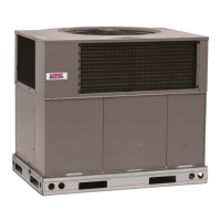
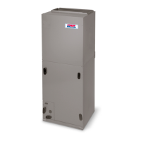
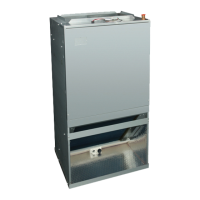
Overview of the product and its installation context.

RECEIVING AND INSTALLATION

Procedures for receiving, inspecting, and preparing the unit for installation.

IDENTIFY UNIT

INSPECT SHIPMENT

PROVIDE UNIT SUPPORT

ROOF CURB

SLAB MOUNT

PROVIDE CLEARANCES

FIELD-FABRICATE DUCTWORK

Guidance on creating and installing custom ductwork for the unit.

RIG AND PLACE UNIT

Detailed instructions for safely rigging and positioning the unit.

INSPECTION

RIGGING/LIFTING OF UNIT

Safety checks and procedures for lifting the unit.

CONNECT CONDENSATE DRAIN

Steps for connecting the condensate drain line to ensure proper drainage.

INSTALL DUCT CONNECTIONS

Procedures for connecting supply and return ductwork to the unit.

INSTALL ELECTRICAL CONNECTIONS

HIGH-VOLTAGE CONNECTIONS

Detailed steps for connecting the main power supply to the unit.

SPECIAL PROCEDURES FOR 208-V OPERATION

Specific adjustments for operating the unit at 208V.

CONTROL VOLTAGE CONNECTIONS

Guidance on connecting low-voltage wiring for thermostats and controls.

STANDARD CONNECTION

Typical low-voltage wiring connections for thermostat control.

PRE-START-UP

CHECK FOR REFRIGERANT LEAKS

Procedure to identify and repair refrigerant leaks.

START-UP

CHECK COOLING AND HEATING CONTROL OPERATION

Verifying the proper functioning of heating and cooling controls.

START-UP ADJUSTMENTS

CHECKING AND ADJUSTING REFRIGERANT CHARGE

Method for verifying and adjusting the refrigerant charge for optimal performance.

INDOOR AIRFLOW AND AIRFLOW ADJUSTMENTS

Procedures for setting and adjusting indoor airflow for cooling and heating modes.

SEQUENCE OF OPERATION

CONTINUOUS FAN

How the unit operates in continuous fan mode.

COOLING MODE

Description of unit operation in low stage and high stage cooling.

ELECTRIC HEATING MODE

How the unit operates when using electric heating.

HEAT PUMP HEATING

Description of unit operation in low and high stage heat pump heating.

HEAT PUMP HEATING WITH AUXILIARY HEAT

Operation details when auxiliary heat is used with the heat pump.

DEFROST MODE

Explanation of how the unit enters and exits defrost mode.

DEFROST CONTROL

QUIET SHIFT

Feature to reduce noise during defrost cycle initiation and termination.

DEFROST

Information on the defrost thermostat and control.

MAINTENANCE

AIR FILTER

Instructions for inspecting and replacing the air filter.

INDOOR BLOWER AND MOTOR

Procedures for cleaning the indoor blower motor and wheel.

OUTDOOR COIL, INDOOR COIL, AND CONDENSATE DRAIN PAN

OUTDOOR FAN

Instructions for inspecting and cleaning the outdoor fan assembly.

ELECTRICAL CONTROLS AND WIRING

Annual inspection of electrical components and wiring connections.

REFRIGERANT CIRCUIT

EVAPORATOR AIRFLOW

Checking airflow for proper unit performance.

METERING DEVICE

Description of the fixed orifice and TXV metering devices used.

PRESSURE SWITCHES

Explanation and checking of low and high pressure switches.

LOSS OF CHARGE SWITCH

Function and checking of the low-pressure loss of charge switch.

REFRIGERANT

Safety information and compatibility notes for R-410A refrigerant.

COMPRESSOR OIL

Information on the type of oil used in the scroll compressor.

SYSTEM INFORMATION

CHECK DEFROST THERMOSTAT

Location and function of the defrost thermostat.

TROUBLESHOOTING

Reference to the troubleshooting chart for diagnosing issues.

START-UP CHECKLIST

Reference to the checklist for initial unit startup procedures.

R-410A QUICK REFERENCE GUIDE

START-UP CHECKLIST

PRESTART-UP

Items to verify before initiating unit operation.

START-UP

Procedures for starting the unit and verifying operation.

ELECTRICAL

Checks for supply voltage and compressor/fan amps.

TEMPERATURES

Measuring outdoor, return-air, and supply air temperatures.

PRESSURES

Measuring suction and discharge pressures and liquid line temperature.

Related product manuals