EasyManua.ls Logo

Heliodyne Delta T Pro - User Manual

Heliodyne Delta T Pro
24 pages
Print Icon
To Next Page IconTo Next Page
Loading...
INSTALLATION
GUIDE
EXCELLENCE
BY DESIGN
DELTA-T PRO
CONTROL UNITS
WIFI + ETHERNET
V. 3.3
WINTER ‘18-’19
Question and Answer IconNeed help?

Do you have a question about the Heliodyne Delta T Pro and is the answer not in the manual?

Summary

OVERVIEW

Safety Guidelines

General safety instructions for installation and use of the controller.

Introduction

Overview of the Delta-T Pro controller's purpose and capabilities.

Models

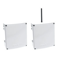
Lists the available Delta-T Pro controller models.

Hardware and Software Requirements for initial setup

Lists the necessary hardware and software for initial setup.

Network Requirements for Monitoring Communication

Details network requirements for controller communication.

Surge Protection Requirements

Explains the necessity of surge protection for the Delta-T Pro.

Relay Wiring

Instructions for wiring relays, emphasizing professional installation.

INSTALL & WIRING

Mounting the Standalone Box

Instructions for mounting the controller box securely indoors.

Controller Inputs and Outputs

Diagram and explanation of the controller's input and output connections.

Power Wiring and LED Indication

Details power wiring and LED indicators for the controller.

230 VAC Switch

Information on adjusting the voltage switch for 230VAC supply.

Relay 1 Wiring and Functionality

Explains wiring and functions of Relay 1.

Relay 2 Wiring and Functionality

Explains wiring and functions of Relay 2.

Relay 3 Wiring and Functionality

Explains wiring and functions of Relay 3.

Sensors

Lists the types of sensors supported by the Delta-T Pro.

Temperature Sensors

Describes the two available mounting styles for thermistor temperature sensors.

Flow rate and pressure Sensors

Details supported flow and pressure sensors and their ranges.

Collector Sensor T1

Purpose and warnings for the T1 collector sensor.

Low Tank Sensor T2

Purpose and warnings for the T2 low tank sensor.

High Tank Sensor T3

Purpose and warnings for the T3 high tank sensor.

T4

Purpose and warnings for the T4 sensor.

T5

Purpose and warnings for the T5 sensor.

Grundfos VFS and T6

Purpose and warnings for Grundfos VFS and T6.

Grundfos RPS and T7

Purpose and warnings for Grundfos RPS and T7.

Additional Functions

Description of additional functions like thermostat detection and relay control.

Thermostat Zone Detection

How to connect thermostats for zone detection and their function.

Variable Speed Current Output

Explanation of 0-10VDC outputs for variable speed pumps.

Pulse Flow Meter Connection

How to connect a pulse flow meter as an alternative to VFS.

Manual Operation of Relays

How to manually control relays (ON, OFF, AUTO).

Manual Reset of Network Parameters

How to reset network parameters using a reset button.

Alternative Purposes at Grundfos Pressure Sensor

Alternative uses for Grundfos pressure signals (CT, pyranometer).

Modbus Connection

How to connect the DTT Pro using Modbus protocol for BAS.

NETWORKING

Network Overview

Overview of internet connectivity via Ethernet/WiFi for monitoring.

Connecting to the controller using the mini-USB port

Steps to connect the controller via mini-USB for setup and monitoring.

Connecting to the controller through local network

How to access the controller UI via IP address on the local network.

Network Setup

Details on setting up Ethernet or WiFi for internet connection and monitoring.

Setup with DHCP with Ethernet connection

Steps to configure Ethernet using DHCP.

Setup with Static IP with Ethernet connection

Steps to configure Ethernet using a static IP address.

Setup with DHCP or Static IP with WiFi connection

Steps to configure WiFi using DHCP or static IP.

Downloading Data to USB Thumb Drive

Instructions for downloading system data to a USB drive.

SETTINGS

Quick Start

Quick setup parameters for basic DHW systems.

SYSTEM

Configuration of system operation modes and parameters.

Settings Login Password

How to change the settings login password.

24 Hour System Clock

Importance and setting of the system clock for data logging.

Modbus Protocol

Enabling RTU or TCP communication via Modbus.

Link

Links for setting up monitoring communication and downloading data.

OPERATION Tab

Section detailing operation settings and parameters.

Solar Relay Box

Settings and parameters for Solar Relay operation.

Relay Two Aquastat Operation (Closed loop Combination System Only)

Using Relay 2 in aquastat operation for specific system types.

Relay Three Operation: Gas Tank Operation

Configuration for using Relay 3 for gas tank operation.

Relay Three Operation: Timer Relay Operation

Configuring Relay 3 for timer-based operation.

Relay Three Aquastat Operation

Using Relay 3 in aquastat operation.

Relay Three Operation: Simple Differential Operation

Configuring Relay 3 for simple differential operation.

SENSORS AND METERING Bar

Configuration for sensors and metering for energy calculation.

System Metering Box

Settings for sensors and metering for energy calculation.

Sensor Naming Box

How to rename temperature sensors in the UI.

Electricity Monitoring Box

Settings for monitoring electricity usage with CTs.

Insolation Monitoring Box

Settings for monitoring solar insolation with a pyranometer.

Firmware update

Steps to update the controller's firmware.

MONITORING

Overview

Overview of local and web-based monitoring capabilities.

Local Monitoring

Details on local monitoring of sensor and energy data.

ENERGY Page

Description of the ENERGY page for sensor and energy data.

SETTINGS Page - Download System Sensor and Historical Data

Downloading historical data from the SETTINGS page.

Heliodyne Web Monitoring

Information on the Heliodyne Web Monitoring service.

Monitoring Setup

Steps to set up the controller for Heliodyne Web Monitoring.

Monitoring Platform Flash Plugin

Information on enabling the Flash plugin for web monitoring.

TROUBLESHOOTING

Delta-T Pro Testing and Troubleshooting

General guidance for testing and troubleshooting the Delta-T Pro.

Testing Controller Logic

Methods for testing controller power, relays, and sensors.

Troubleshooting Communication and Network Issues

Solutions for common communication and network connection problems.

Troubleshooting Operation

Solutions for common operational issues like sensor readings and pump control.

WARRANTY

Warranty Details

Detailed warranty terms and conditions for Heliodyne products.

Overview

The Heliodyne Delta-T Pro Control Unit is a sophisticated controller designed for solar thermal systems, offering comprehensive management for domestic hot water, space heating, industrial process heating, and general heat metering applications. It is available in two models: an Ethernet-only version (DLTA 000 005) and a Wi-Fi + Ethernet version (DLTA 000 008).

Function Description:

The Delta-T Pro controller's primary function is to optimize solar thermal system performance by managing pumps and valves based on temperature differentials and other system parameters. It supports various operating modes, including Open Loop Residential DHW, Closed Loop Residential DHW, Closed Loop Commercial, Closed Loop Combination, and Closed Loop Pool Heating. Each mode comes with default parameter profiles optimized for specific system types.

The controller features a user interface accessible via a PC or Mac through its mini-USB port or by accessing its assigned IP address with a web browser. When connected to the internet, it can transmit data to the Heliodyne monitoring site for remote data logging, allowing users to view and download system performance in terms of temperature, flow rate, pressure (optional), and instantaneous and time-integrated energy production.

Important Technical Specifications:

  • Power Supply: The control unit is designed for 115VAC, 10A systems, with an option for 230VAC supply. Board revision 11 and later models auto-detect the applied voltage.
  • Relay Specifications:
    • Relay 1 (N.O. & N.C.): Contact Voltage 115 or 230V, Max Ratings 1HP, 115V; 2HP, 230V [N.O.], 1/4 HP, 115V; 1/2HP, 230V [N.C.]. This relay is typically used for solar operation pumps in dual-pump systems and can also power components operating opposite to solar operation.
    • Relay 2 (N.O.): Contact Voltage 115 or 230V, Max Ratings 1/4 HP, 115V; 1/2HP, 230V. This relay can operate a pump or valve in Space Heating Mode or power the domestic water circulator independently in Dual Pump Mode.
    • Relay 3 (N.O.): Contact Voltage 115 or 230V, Max Ratings 1/4 HP, 115V; 1/2HP, 230V. This relay can be used for Electric Ignition Gas Tank Operation, Timer Operation, Aquastat Operation, or Simple Differential Operation.
  • Sensor Inputs: The Delta-T Pro can read four types of sensors:
    • 10kΩ Thermistors: Used for temperature measurement (T1-T7).
    • Grundfos VFS (Vortex Flow Sensor): Measures flow rate and includes an embedded temperature sensor. Supported ranges: 0.25 to 106 GPM.
    • Grundfos RPS (Relative Pressure Sensor): Measures pressure (0 to 150 psi) and includes an embedded temperature sensor.
    • Pulse Flow Sensors: Used for flow rate measurement, producing a square-wave pulse with a pull-up to positive DC voltage of 3VDC.
  • Additional Inputs/Outputs:
    • Digital Flow/Temperature and Digital Press/Temperature inputs.
    • Pulse Flow Meter (10 VDC Supply).
    • 4-20 mA Output Controlled Current: Two 0-10VDC output signals for variable speed pumps.
    • 24 VAC Thermostat Zone Detection (Z1-Z4): For space heating mode.
    • MODBUS port: For communication with Building Automation Systems (BAS).
    • Touchscreen Port (HCOMs only).
    • USB port: For local monitoring and data download to a USB thumb drive.
    • Ethernet and Wi-Fi connectivity: For internet connection and remote monitoring.
  • Memory: Contains battery-backed SRAM for protecting system clock, settings, and data during power outages.
  • Network Requirements: Consistent internet connection, DHCP enabled network or available static IP address, TCP communication on port 9999. Wi-Fi supports 802.11b/g/n with Open, WPA-personal, WPA2-personal (WEP or WPA/WPA2-ENTERPRISE are not supported).

Usage Features:

  • Mounting: Designed for indoor wall mounting, away from weather and electrical interference, and out of direct sun in a cool, dry location. A screw template is provided for secure installation.
  • User Interface: Intuitive web-based interface for system setup, monitoring, and data visualization, including temperature sensor history, flow rate history, energy rate, relay states, and system date/time.
  • Configuration: Allows adjustment of various parameters such as On/Off differentials, tank high limit, glycol concentration, vacation mode, freeze recirculation, and drain back options.
  • Relay Operation Modes:
    • Aquastat Operation (Relay 2 & 3): Control based on a set temperature point, with heating or cooling modes, low limit, and hysteresis.
    • Gas Tank Operation (Relay 3): For electric ignition gas-fired solar storage tank systems, managing recovery rate, set temperature, and estimated hot water demand.
    • Timer Relay Operation (Relay 3): Turn the relay on and off at set hours during the day.
    • Simple Differential Operation (Relay 3): Operate a secondary differential using user-selected sensors and conditions.
  • Sensor Naming: Customizable labels for temperature sensors (T1-T7) within the controller's user interface.
  • Electricity Monitoring: Can monitor main circuit voltage, CT full scale values, tank element voltage, and power frequency using current transformers connected to the Grundfos Pressure Sensor inputs.
  • Insolation Monitoring: Can monitor solar radiation using pyranometers connected to the Grundfos Pressure Sensor inputs.
  • Firmware Updates: Easy firmware upgrade process through the web interface by uploading a .deb file.
  • Data Download: System sensor data can be downloaded to a USB thumb drive (16 GB or less) for offline analysis.
  • Network Reset: Manual reset button for network parameters.

Maintenance Features:

  • Safety Guidelines: Emphasizes adherence to National Electric Code, UL certification, and local building codes. Electrical work or modifications must be performed by a qualified professional with power disconnected.
  • Surge Protection: Requires installation of a surge suppressor between the Delta-T Pro and a power source to protect against voltage spikes, current surges, and noise, which can cause data loss or general failure.
  • Troubleshooting: Comprehensive troubleshooting section covering power, relay operation, sensor issues, and communication/network problems, with solutions ranging from checking wiring and settings to driver reinstallation and network configuration adjustments.
  • Warranty: Heliodyne provides a warranty for defects in material and workmanship, with terms varying by product type (5 years for HCOM, HPAK, HFLO, HPAS with Heliodyne collectors; 3 years for Integrated Electronics and Delta-T Products; 10 years for GOBI Collectors). Warranty claims require written notification and proof of purchase/installation. Exclusions include damage from improper installation, misuse, negligence, weather damage, or alterations.

Heliodyne Delta T Pro Specifications

General IconGeneral
BrandHeliodyne
ModelDelta T Pro
CategoryControl Unit
LanguageEnglish