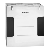
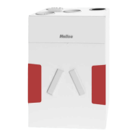
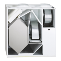
Central ventilation unit – KWL 200/300 W/W ET
Installation and Operating Instructions
ENEN
17
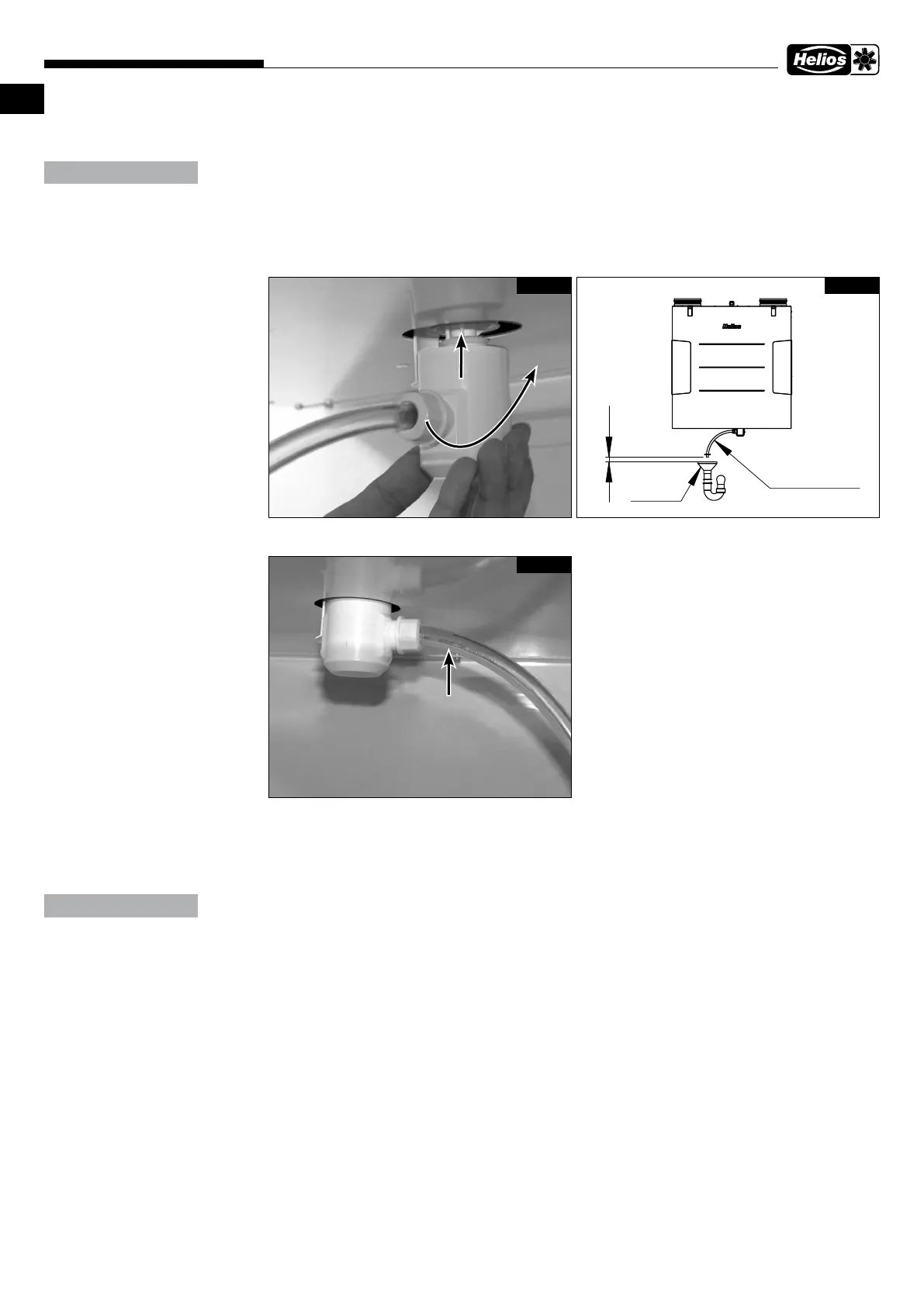
5. Connect siphon casing and turn a 1/4 turn in the mounting part (see Fig. 24). Ensure that the float ball is loose in
the casing!
Water damage in the unit due to condensation.
A closed discharge can lead to pressure conditions which prevent controlled drainage from the unit. Furthermo-
re, gases may escape from the drainage line into the unit, which may create a breeding ground for microorga-
nisms in combination with moisture.
> The condensate hose must end 20 mm above the open drain or possible water level (see Fig. 25).
> The condensate hose from the ball siphon must have a downward gradient, openly dripping into a funnel
siphon and must not be discharged into a closed system (see Fig. 25).
6. Connect condensate hose (length max. 1.5 m) to the building drainage system (see Fig. 26).
7. The ball siphon must be inspected:
– In order to guarantee the absence of leaks, the ball siphon must not be subjected to lateral loads due to the con-
densate hose during installation!
– The drainage pipe route must not rise behind the siphon! Ensure that there are no air pockets during installation!
– The condensate outlet must be frost-proof!
Water damage in the unit due to condensation.
If the “cold recovery” function is activated and the plugs in the condensate tray have not been removed, this can
result in water damage in the unit because the condensate cannot drain freely.
> If the “cold recovery” function is used, the plugs in the condensate tray must be removed.
> The function must be activated or deactivated in the unit control system according to the application.
4.4 Connect ventilation ducts
The units are equipped with four spigots (Ø 125 mm) for connection to the duct system. The ventilation ducts must be
connected firmly and tightly to the spigots. Duct connectors RVBD 125 K (accessories) must be used in this respect.
The arrangement of ventilation ducts (supply air, extract air, intake air and exhaust air) is shown in Fig. 3 and Fig. 4 on
page 9.
ATTENTION
Connect siphon
casing
Fig. 24
1/4 turn
20
Trichter-
siphon
ø12, Schlauch
max.1,5m lang,
Gefälle beachten
Fig. 25
Condensate hose DN 12 mm
(Note gradient!)
Fig. 26
ATTENTION
Funnel siphon
ø 12, hose
max. 1.5 m long
Note gradient
 Loading...