DE DE
MultiVent
®
– MV EC
Montage- und Betriebsvorschrift
17
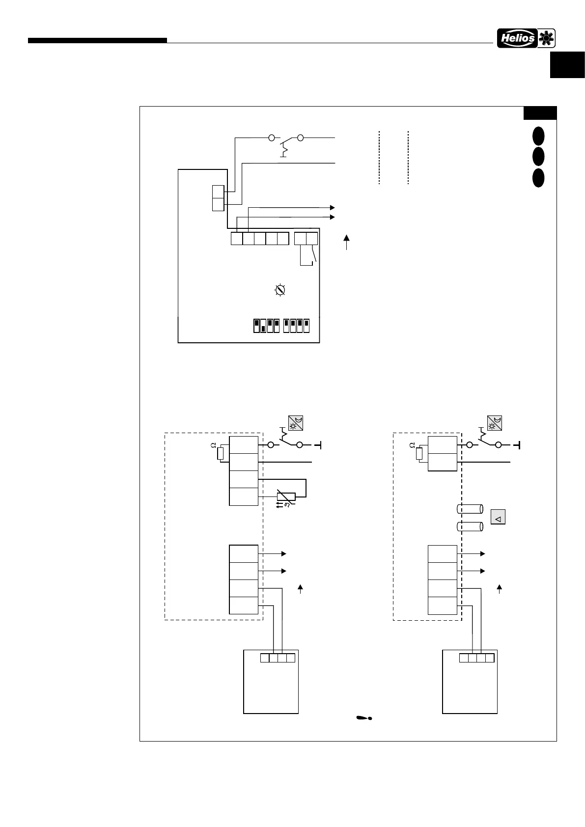
6�3�4 Anschlusspläne mit ETR/EDR
SS-1230
MV EC 100
MV EC 125
MV EC 150
MV EC 160
MV EC 200
MV EC 250
Wechselstrom,
1~, 230 V, 50 Hz
mit ETR/EDR
85490 001 SS-1230 04.12.19
GND
+UB
EDR
GND
A
2
1
+-
p
Ri=4k
GND
+UB
ETR
GND
A
2
1
Setpoint 1/2
10 ..24 VDC (extern)
+
Ri=4k
TF
TF
Setpoint 1/2
10 ..24 VDC (extern)
+
GND
0-10 V
GND
0-10 V
A
GND
ETR / EDR
LN
250 V
3A
N
L
S2
S1
P0
PI
P10
+10V
0-10 V
GND
1
off
on
2
3
4
1
off
on
2
3
4
P1
MV EC 100 - 250
R1
R2
SW2 SW1
2)
3)
1)
+
+
-
-
NG 24
+
+
-
-
NG 24
Art. Nr.: 1439
Art. Nr.: 1439
24V DC
24V DC
D
E F
Detailplan SS-1040
detail plan/plan détaillé
Detailplan SS-1039
detail plan/plan détaillé
EC-Motor
moteur EC
control cables max. 30m, shielded from 20m, see Installation and Operating Instruction !
Steuerleitungen max. 30m, ab 20m abgeschirmt, siehe Montage- und Betriebsvorschrift !
Cables de commande max. 30m, blindés à partir de 20m, voir Notice d’installation et de montage !
EC-Motor
moteur EC
Revisionsschalter
bauseits zu stellen
Isolation switch
to be provided by
customer
interrupteur de
(fourniture client)
resp.
Abb�30
 Loading...