EN EN
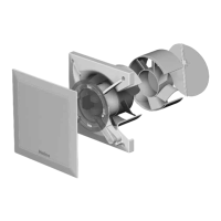
MultiVent
®
– MV EC
Installation and Operating Instructions
14
PENL1
1~ 230V
50/60 Hz
85499 055 SS-1293 13.08.19 S.2
24V
GND
LDF 500
Pressure transducer
Art.Nr. 1322
br
ge
ws
LDF
0-10V
USB
PE
N
L1
11
max 2A (resistive load)
250VAC
EUR EC, Art.Nr. 1347 002
K1
K2
J1
7
2B
1B
GND
2A
24V
D2
D1
A1
A2
GND
GND
E1
E2
14 12 21 24 22
ID
1A
GND
T
T
MV EC 315
SW1
250 V
3A
N
L
S2
S1
P0
PI
P10
+10V
0-10 V
GND
1
off
on
2 3 4
1
off
on
2 3 4
P1
L
N
R1
R2
SW2
4 3 L2 N1
Cover
1)
2)
3)
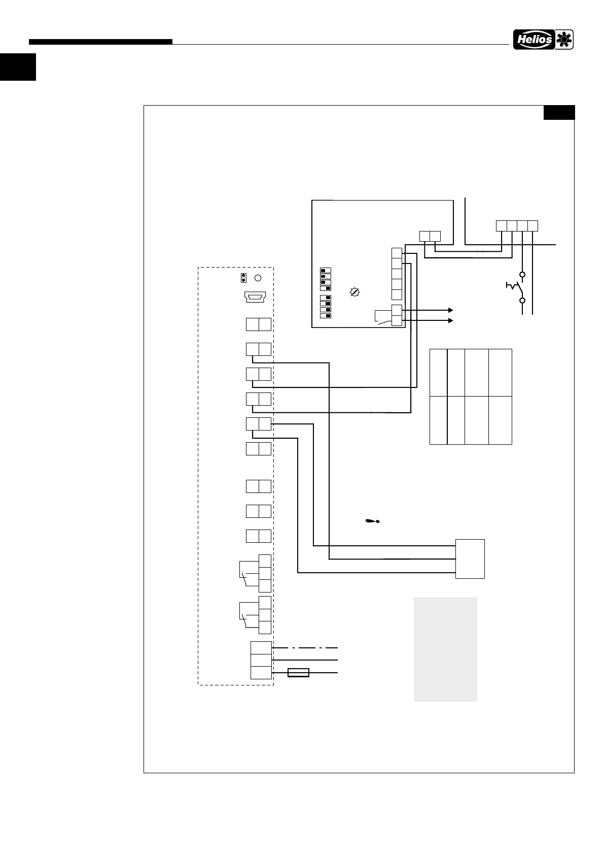
Example: EUR EC controls MV EC 315 (SS-1195), with mode 4.01 (pressure controlled)
EUR EC settings
Sensor input E1:
Base setup/
Mode 4.01=pressure control
Analog output A1:
IO Setup/
A1 function, 2A=proportional modulation
Control cables
max. 30m, shielded from
20m, see installation
and operating instructions !
Operating message
Relay contact
terminal R1-R2
Fan without
mains supply
open
Fan with
mains supply,
fan rotates
1)
Fan with
mains supply,
Fan is stopped
2)
closed
open
1) With setpoint specification and without fault
2) Without setpoint specification or with fault
Condition fan
Isolation switch
to be provided by
customer
Fig�27
SS-1293
MV EC 315
Alternating current,
1~, 230 V, 50 Hz
with EUR EC
 Loading...