EN EN
MultiVent
®
– MV EC
Installation and Operating Instructions
20
8�1 Information – Fault causes
The triggering of the integrated electronic temperature monitoring system can be caused by:
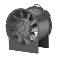
– the build-up of dirt, stiness of impeller and/or ball bearing failure
– air flow temperature too high
– electronic error
Abnormal noises can be caused by
– worn out ball bearings
– lack of vibration decoupling to other buildings and ducting systems
Vibrations and oscillation can be caused by:
– unbalanced or dirty impellers
– lack of vibration decoupling to other buildings and ducting systems
Extreme reductions in performance can occur
– if resistance to air stream through ducting and accessories (grilles, shutters, filters etc.) is higher than planned.
CHAPTER 8
FAULT CAUSES
 Loading...