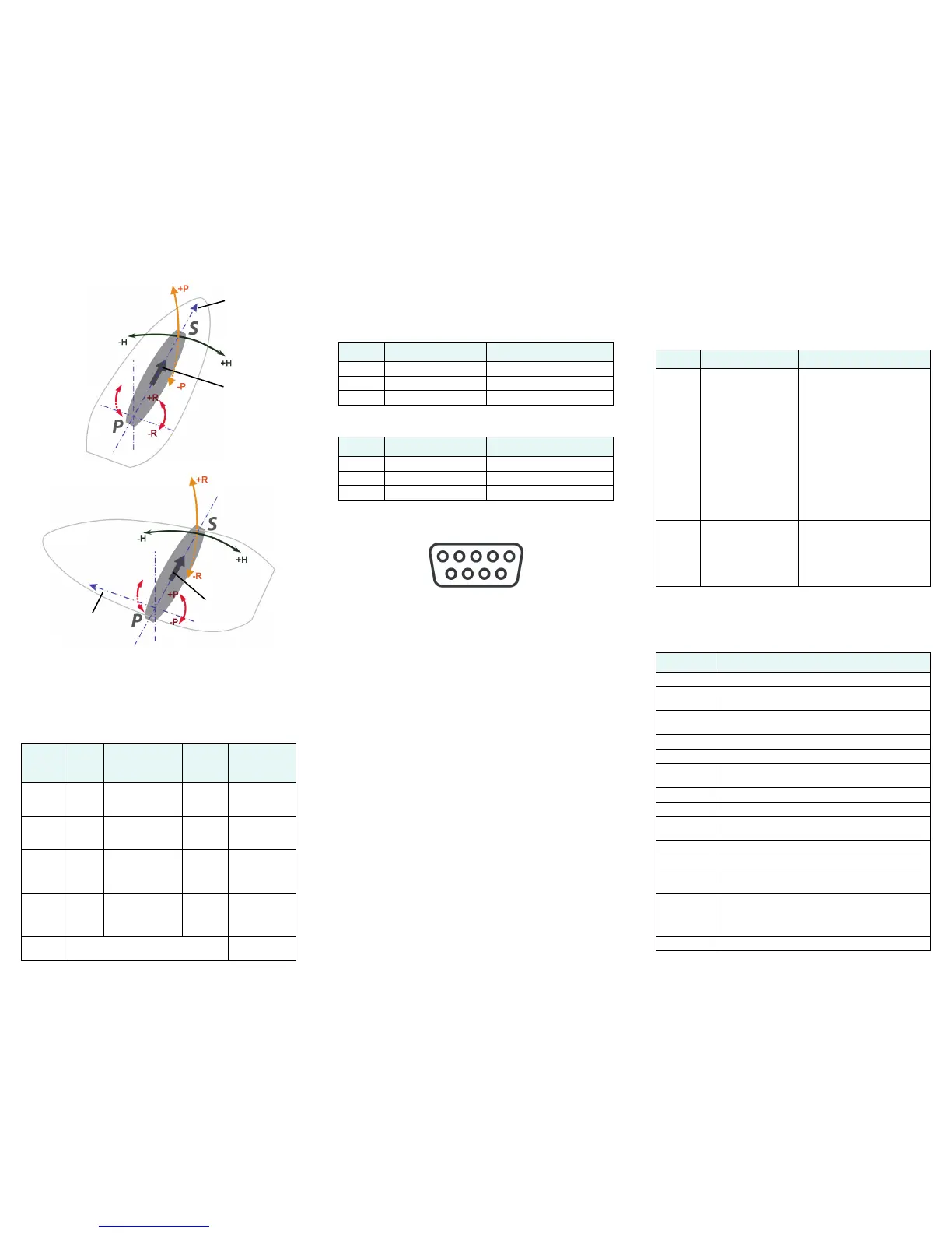
Mounting Orientation
Wiring Interface
The following table provides Information for the 15 m
cable and 30 m cable.
Serial Port Connection
Connect the wires to a DB9 female socket using either
the port A or port B configuration.
DB9 Female Socket Numbering
Configuration
Use a terminal program, or PocketMAX, to connect to a
serial port for additional configuration requirements. Use
default baud rate of 19200 bps and 8-N-1 protocol.
• Change baud rate of either port to match that of
the external equipment to which the V101/111 is
connected. After changing the baud rate, you
must close the terminal program and reconnect
at the speed selected.
• Configure NMEA messages to be output on the
appropriate port.
• Select differential source (BEACON is the default
on the V111).
• Input heading bias (-180° to +180°) to
compensate for any offset from the centerline.
• Input bias for tilt (-15° to +15°) to compensate for
any offset from horizontal.
• Enable/disable supplementary sensors (default
is GYROID and TILTAID on).
• Use the $JSAVE command to save the
configuration changes when finished.
Supplemental Sensors
A tilt sensor and gyro are integrated in the V101/111. The
user can turn either on or off. However, the system’s
performance is optimized with both on.
Common Commands and Messages
Port
Baud
Rate
NMEA
Messages
Default
Update
Rate
Wires
Port A
(RS-232)
19200 GPGGA, GPVTG,
GPGSV, GPZDA,
GPHDT, GPROT
1 Hz BLU
BLK with BLU
Port B
(RS-232)
19200 GPGGA, GPVTG,
GPGSV, GPZDA,
GPHDT, GPROT
1 Hz BRN
BLK with BRN
Port A
(RS-422)
output
only
19200 GPGGA, GPVTG,
GPGSV, GPZDA,
GPHDT, GPROT
1 Hz GRN
BLK with
GRN
Port B
(RS-422)
output
only
19200 GPGGA, GPVTG,
GPGSV, GPZDA,
GPHDT, GPROT
1 Hz YLW
BLK with YLW
Power 9 - 36 VDC RED (+)
BLK (-)
Forward
motion
Parallel
Orientation
Forward
motion
Recessed arrow
located on
bottom of
enclosure
(recommended
orientation and
resulting signs
of HPR values)
Recessed arrow
located on
bottom of
enclosure
Perpendicular
Orientation
(alternate
orientation and
resulting signs
of HPR values)
Port A DB9 RS-232 interface configuration
Pin Wire Color Signal
2 Blue Port A transmit RS-232
3 Black/blue striped Port A receive RS-232
5 Gray Signal ground
Port B DB9 RS-232 interface configuration
Pin Wire Color Signal
2 Brown Port B transmit RS-232
3 Black/brown striped Port B receive RS-232
5 Gray Signal ground
Sensor Purpose Calibration Procedure
Gyro
aid
Smooth rate of turn:
• Provides alternate
source of heading
for up to three
minutes when GPS
lock is lost
• Shortens heading
reacquisition time
Will self-calibrate after several
minutes
To manually calibrate:
• After heading is computed
• $JATT,GYROAID,YES
• Spin Vector for one minute
at less than 15º per second
• Leave unit stationary for
four minutes
Note: It is not necessary to
recalibrate with standard use
because the gyro selects the
calibration.
Tilt aid • Smooths rate of
heading
• Reduces startup
and reacquisition
times for obtaining
heading
Precalibrated during
manufacture
To recalibrate:
• Ensure Vector is level
• $JATT,TILTCAL
Commands
Command Description
$GPMSK Tune beacon to specific frequency
$J4STRING Output GPGGA, GPVTG, GPGSA, GPZDA (1Hz
max)
$JAGE Specify maximum DGPS (COAST) correction age (6
to 8100 seconds)
$JAPP Query or specify receiver application firmware
$JASC Specify ASCII messages to output to specific ports
$JBAUD Specify RS-232, RS-422 (output) communication
rate
$JBIN Specify binary messages to output to specific ports
$JDIFF Query or specify differential correction mode
$JGEO Query or specify SBAS for current location and
SBAS satellites
$JI Query unit’s serial number and firmware versions
$JOFF Turn off all data messages
$JQUERY,
GUIDE
Query accuracy suitability for navigation
$JRESET Reset unit’s configuration to firmware defaults.
$JRESET clears all parameters. See the V101
and V111 GPS Compass User Guide for more
information.
$JSAVE Save session’s configuration changes
 Loading...