Do you have a question about the HERO EUREKA A450 and is the answer not in the manual?
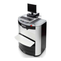
Identifies the personal computer component of the dispenser.
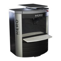
Highlights the platform for placing cans during the dispensing process.
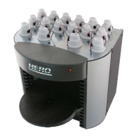
Marks the access point for colorant canisters.
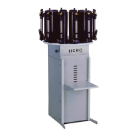
Indicates the location of colorant storage canisters.
Points to the controls for the telescopic elevator mechanism.
Locates the critical button for immediate machine stoppage.
Identifies the outlets where colorants are dispensed.
Designates the adjustable surface for the computer.
Identifies the pumps responsible for dispensing colorant cartridges.
Locates the main circuit board controlling machine functions.
Shows the points for electrical grounding for safety.
Indicates the primary power control and connection.
Highlights the cable used for data transfer and connection.
Specifies the recommended operating temperature range for the dispenser.
Defines the acceptable range of humidity for proper operation.
Emphasizes the necessity of an efficient electrical grounding system.
Provides critical instructions for safe machine operation and maintenance.
Details on how to place the machine for optimal performance and ventilation.
Steps involved in safely removing the dispenser from its packaging.
Procedure for removing the machine from its shipping pallet.
Guidance on final placement using wheels and levelling feet.
Instructions for positioning the PC, monitor, and keyboard, and connecting them via USB.
Details on connecting the USB cable between the dispenser and the PC.
Advice on using the upper shelf for PC placement to prevent spills.
Steps for connecting power to the machine and PC, and powering them on.
Procedure for installing the provided software on the PC.
Instructions for filling the colorant tanks, emphasizing caution.
Requirement for calibration before using the machine, needing a precision scale.
Detailed steps for safely disconnecting and replacing a cartridge pump.
Explains the automatic cap's role in preventing colorant exsiccation.
Steps for removing and installing a new automatic cap without tools.
Importance of keeping the sponge clean and humid for optimal performance.
Describes the elevator's role in lifting the can plane and positioning cans.
Step-by-step guide for replacing the telescopic elevator column.
Explains the board's role in simultaneous dispensing and its extractable design.
Detailed steps for safely removing and replacing the simultaneous PCB.
Details the board's function for sequential dispensing and its extractable design.
Detailed steps for safely removing and replacing the sequential PCB.
Starts the 'empty dispense tube' operation through the machine's software.
Chooses specific circuits to be emptied using the software interface.