11
reaches the set value of “MaxTemp. T2 OFF collector’s pump”. Additionally, in order to avoid unstable pump operation when the temperature on the temperature sensor changes,
switch on and switch off hysteresis has been used.
ATTENTION! In case of simultaneous operation of the P pump and the K pump, the current value of the PWM control signal is determined by the higher temperature
difference.
Controlling the C circulation pump
Similarly as in scheme no 2 - description in point 4.2.
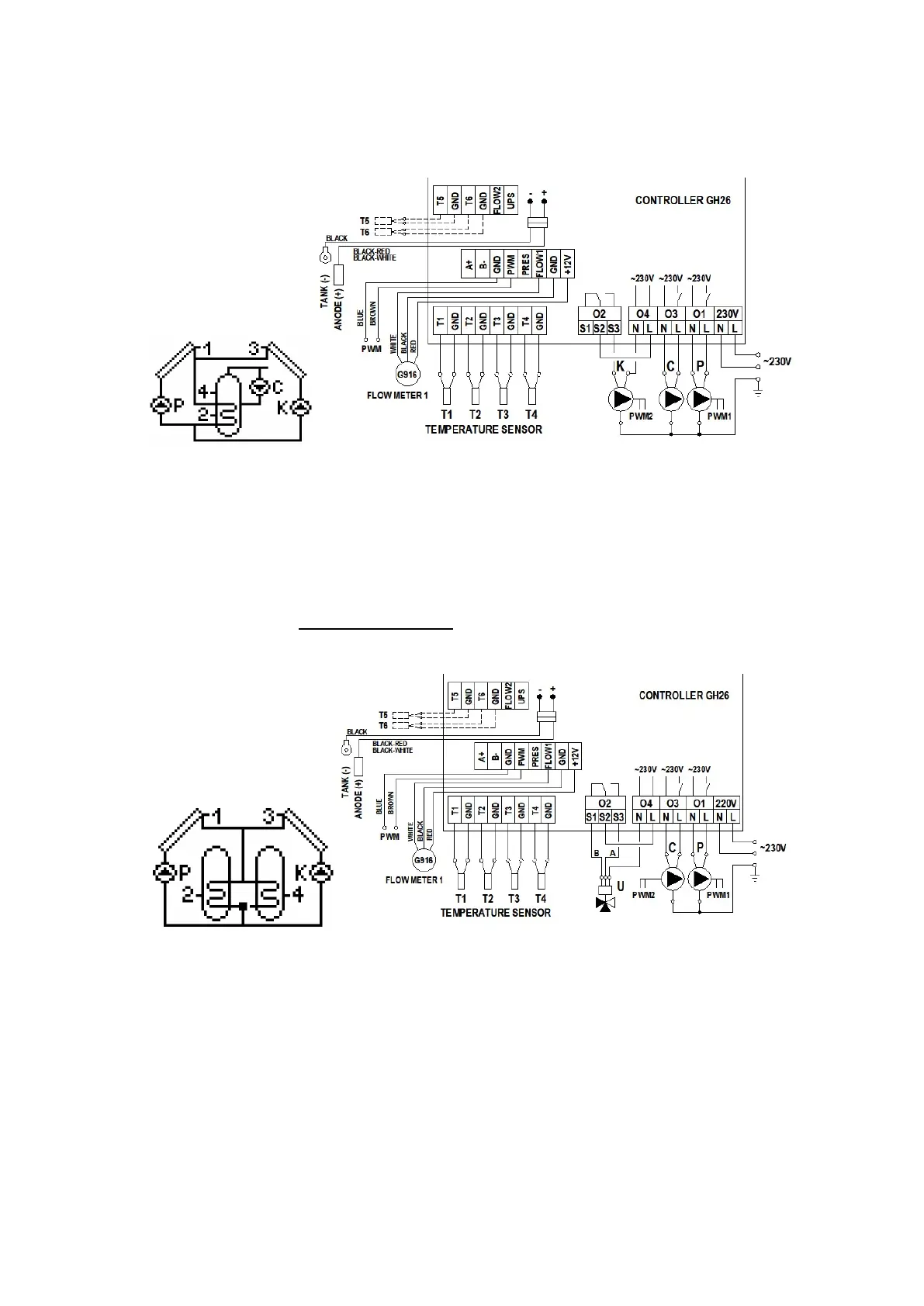
Fig. 17. Schematic and electrical diagram of installation no 15.
4.16 Double-heater system using a three-way valve - controlling operation of solar collector pumps located in various directions - scheme no 16
Controlling P and K collector pumps and the U three-way valve – selected priority: B > A.
Solar heating of B heater is analogical as in scheme no 15, and described in point 4.15.
The A heater is the second heat receiver. If the user-set temperature “MaxTemp. T2 OFF collector’s pump” is reached, the controller will automatically start heating water in the A
heater. This is done by switching the U three-way valve into the A heater direction if the T1 solar collector temperature gets higher, by the value of “Temp. T1&T2 difference – pump
ON”, than the T4 temperature in A heater. The pump remains switched on until the difference in temperatures (T1-T4) falls below the set value and the temperature in the A heater
reaches “Max. temp. T4 OFF heat source”. When the T4 temperature exceeds the set value, the controller switches the valve back into the B heater direction and switches the P
collector pump off. When water is being heated in the A heater, once an hour for 5 minutes the controller forces P collector pump switch off in order to check the conditions for heating
the B heater and switch heating back to B heater. K collector pumps work analogically.
ATTENTION ! Operation of two heaters, A and B, has been described for priority B >A. If priority A > B is set, the heating plan is the reverse of the one presented above.
Selecting priority B will result in similar operation as in scheme no 9 for both pumps – description in point 4.9.
Fig. 18. Schematic and electrical diagram of installation no 16.
4.17 Tap water heating system - controlling solar collector pump, circulation pump and a heater cooling system - scheme no 17
Controlling the P collector pump
Similarly as in scheme no 1 - description in point 4.1.
Controlling the C circulation pump
Similarly as in scheme no 2 - description in point 4.2.
Controlling the heater cooling system with the use of the K release valve
The K release valve gets open if the T4 temperature of the upper part of the heater reaches the value of the set “Max. temp. T4 OFF heat source” parameter.
Closing the release valve (switching the electrical equipment off) will take place when the T4 temp. in the upper part of the heater is reduced by 10°C.
For example: switch on, T4 temp. increase to above 60°C – switch off, T4 temp. decrease to below 50°C.
 Loading...