12
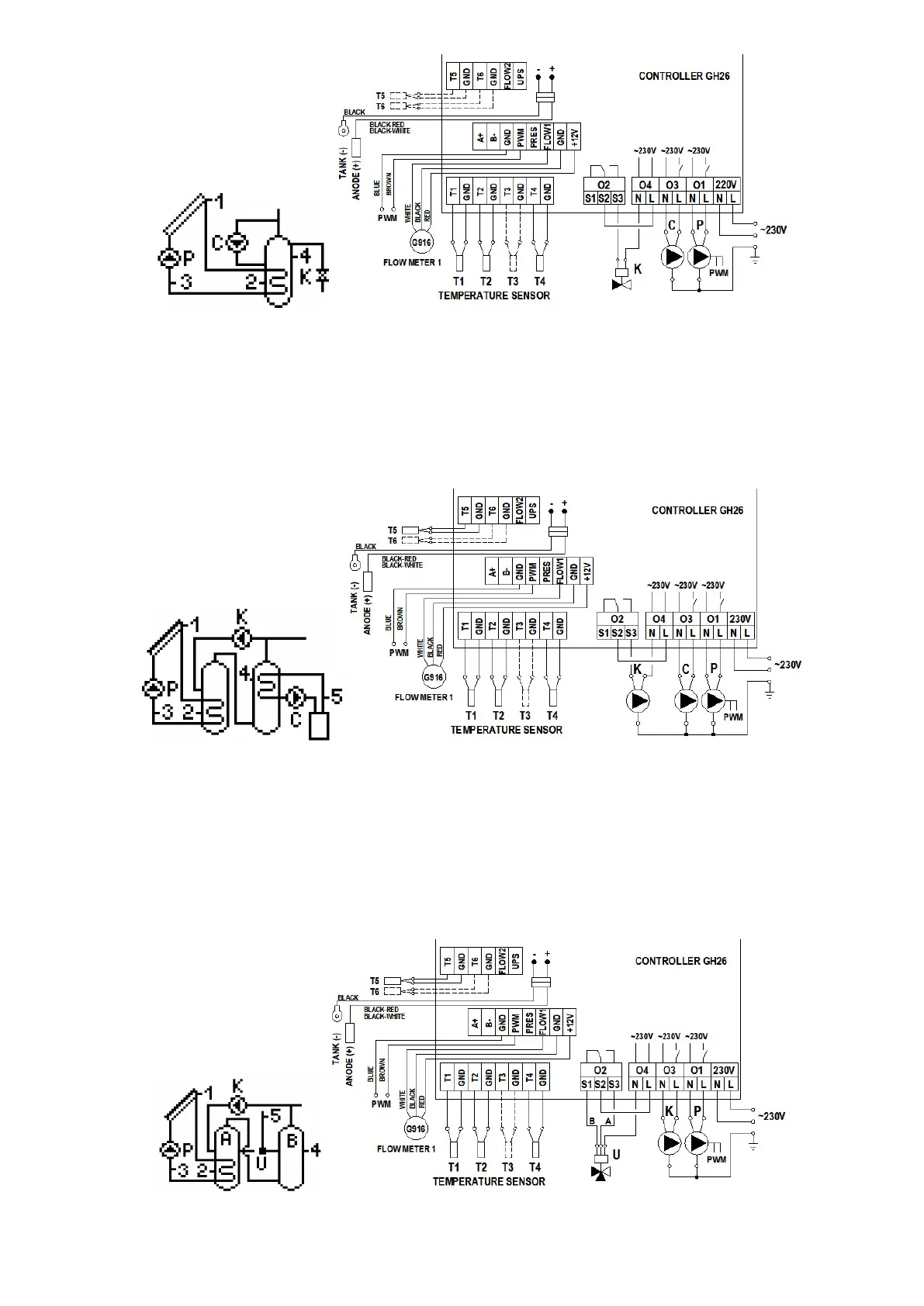
Fig. 19. Schematic and electrical diagram of installation no 17
4.18 Tap water heating system – controlling solar collector pump, solar energy heating for the boiler heater with the use of a pump and controlling the operation of
fireplace or solid-fuel boiler pump – scheme no 18
Controlling the P collector pump
Similarly as in scheme no 1 – description in point 4.1.
Controlling the K mixing pump
Similarly as in scheme no 7 – description in point 4.7.
Controlling the C solid-fuel boiler pump
Similarly as in scheme no 6 (the pump in scheme 6 is denoted by K) – description in point 4.6.
Fig. 20. Schematic and electrical diagram of installation no 18.
4.19 Tap water heating system – controlling solar collector pump, mixing pump and system of solar energy heating for the boiler heater with the use of a circulation
return – scheme no 19
Controlling the P collector pump
Similarly as in scheme no 1 – description in point 4.1.
Controlling the K mixing pump
Similarly as in scheme no 7 – description in point 4.7.
In addition, the pump operation depends on enabling the protection against Legionella function and results in heating the solar heater while the function is active if the boiler heater is
heated up to at least 60C.
Controlling the U three-way valve
Similarly as in scheme no 8 – description in point 4.8.
Fig. 21. Schematic and electrical diagram of installation no 19.
 Loading...