7
Fig. 8. Schematic and electrical diagram of installation no 6.
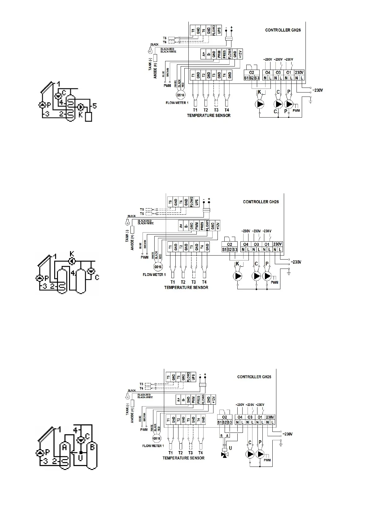
4.7 Double heater system - makes it possible to provide additional solar energy for the boiler heater with the use of a mixing pump - scheme no 7
Controlling the P collector pump
Similarly as in scheme no 1 - description in point 4.1.
Controlling the C circulation pump
Similarly as in scheme no 2 - description in point 4.2.
Controlling the K mixing pump
The K mixing pump will be switched on if the T2 temperature at the collector heater gets higher by the “Temperature difference ON add. pump, valve” value than the T4
temperature in the boiler heater. The pump will remain switched on until the difference in temperatures (T2-T4) falls below the set value and the temperature in the boiler heater
reaches the set allowable value of “Max. temp. T4 OFF heat source”.
Fig. 9. Schematic and electrical diagram of installation no 7.
4.8 Double heater system - makes it possible to provide additional solar energy heating for the boiler heater with the use of a circulation return - scheme no 8
Controlling the P collector pump
Similarly as in scheme no 1 - description in point 4.1.
Controlling the C circulation pump
Similarly as in scheme no 2 - description in point 4.2.
Controlling the U three-way valve.
The three-way valve will be switched into the A heater direction if the T2 temperature at the collector heater gets higher by the “Temperature difference ON add. pump, valve” value
than the T4 temperature in the circulation return. The valve will switch into the direction of A heater if the difference in temperatures (T2-T4) falls below the set value. Else, circulation
return will always be directed to the B boiler heater.
Fig. 10. Schematic and electrical diagram of installation no 8.
 Loading...