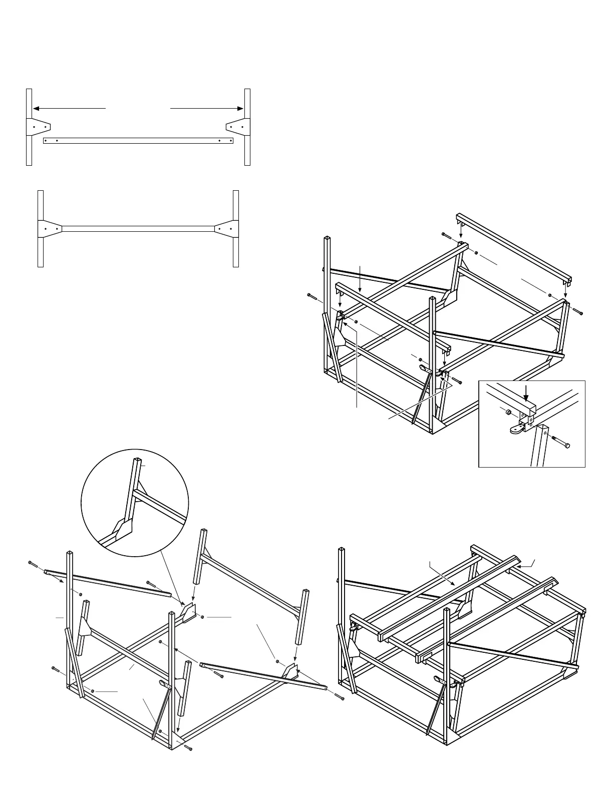
STEP 3
Assemble "H" Cross Bars and Uprights. Use four
3/8" x 2-3/4" bolts for each "H". Front and rear
assemblies are identical.
STEP 5
Attach 2-link chains to the two remaining teardrop pulleys.
(Do not overtighten pulley side plates – pulleys must turn
freely).
Position Pull arms to the inside of the "H" frames. Posi-
tion Bed Cross Beams so that holes in "U" brackets are in
line with the holes in the top of the "H" frames and the Pull
Arms. Join parts at each corner with a 1/2" x 4-1/2" bolt
and 1/2" lock nut.
As you run the bolt through each front corner, insert the
chain of one pulley assembly into the end of the Pull Arm
so the bolt passes through the free link of the chain.
Important: Do not overtighten lock nuts. Pull arms and
Cross beams must move freely for proper lift operation.
"H" CROSS BAR
"H" UPRIGHTS
STEP 4
Place bottom ends of one "H" frame between Corner Post
side plates and secure with two 1/2" x 3" bolts and two 1/2"
lock nuts. Attach front ends of 45° Angle Braces to the Cor-
ner Posts using two 3/8" x 3-3/4" bolts and two 3/8" nuts.
Place bottom ends of second "H" frame between Long
Base side plates, align 45° Angle Braces and secure with
two 1/2" x 4-1/2" bolts and two 1/2" lock nuts. (Note: "H"
frames may be laid flat for easier assembly).
Important: Do not overtighten lock nuts. "H" frames must
move freely for proper lift operation.
"H" FRAME
45ϒ ANGLE
BRACE
45ϒ ANGLE
BRACE
"H" FRAME
1/2" x 3"
1/2" x 3"
1/2" Lock
Nuts
3/8" x 3-3/4"
1/2" x 4-1/2"
3/8" x 3-3/4"
1/2" Lock
Nuts
1/2" x 4-1/2"
CORNER
POST
LONG BASE
PULL
ARM
PULL
ARM
PULLEY WITH
2-LINK CHAIN
BED CROSS
BEAM
BED
CROSS
BEAM
1/2" x 4-1/2"
1/2" x
4-1/2"
1/2" x 4-1/2"
1/2" Lock
Nuts
1/2" x
4-1/2"
1/2" Lock
Nuts
STEP 6
Attach Bunk Brackets to Wood Bunks using four 3/8" x
2-1/2" carriage bolts and four 3/8" nuts. Place Bunks with
brackets over the Bed Cross Beams. Adjust placement
for width of watercraft and secure brackets to Bed Cross
Beams using four 3/8" x 2-3/4" bolts and four 3/8" nuts.
Rear "H" frame must
be installed as shown
for the lift to lower
completely.
PLATE
ON BACK
SIDE
1/2"
Lock Nut
1/2" x
4-1/2"
Bolt
PULLEY
with 2-link
chain
(2)
3
/
8
" x 2-
3
/
4
"
Bolts
(2)
3
/
8
" x 2-
3
/
4
"
Bolts
PAGE 2
 Loading...