echo series Product manual
9 WWW.HEXMAN.CN
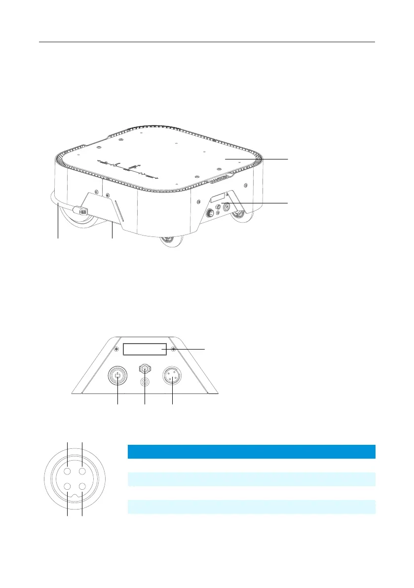
2.1 Architecture Introduce
This section will provide a basic introduction to the chassis, facilitating users and
developers to have a basic understanding of the chassis. As shown in Figure 2.1, it is an
overview view of the entire mobile robot chassis
Figure 2.1 Overview View
2.2 Electrical Interface Description
The rear electrical interface is shown in Figure 2.2. 1 is the power display module; 2 is the
power switch; 3 is the CAN communication and 24V power expansion port; 4 is the battery
charging port.
1. Anti-collision strip
2. Handling space
3. Extension panel
4. Electrical panel
Figure 2.2 Electrical Panel View
Figure 2.3 Aviation Plug Pin Diagram
1. Voltage and electricity display
2. Power switch
3. Aviation plug interface
4. Charging interface
3 2
4 1
1 2
3
4
2 4 3
1
Types
Power
Power
CAN
CAN
Pin number
1
2
3
4
Function
VCC
GND
CAN-H
CAN-L
Notes
Positive(22V~29V)5A MAX
Negative pole
CAN HIGH
CAN LOW
(Note: Vehicle Socket Perspective, Non Data Cable Perspective)