lag manual
www.hex.haus
@hex.haus.hex
info@hex.haus
HEX lag is a digital sound processing instrument with signal modulating
potentiometers and an interactive tactile surface for direct sound manipulation.
It digitally simulates analogue bucket brigade delay chips (typical of chorus,
flanger and karplus-strong), but also enables pitch-shifting, downsampling, etc.
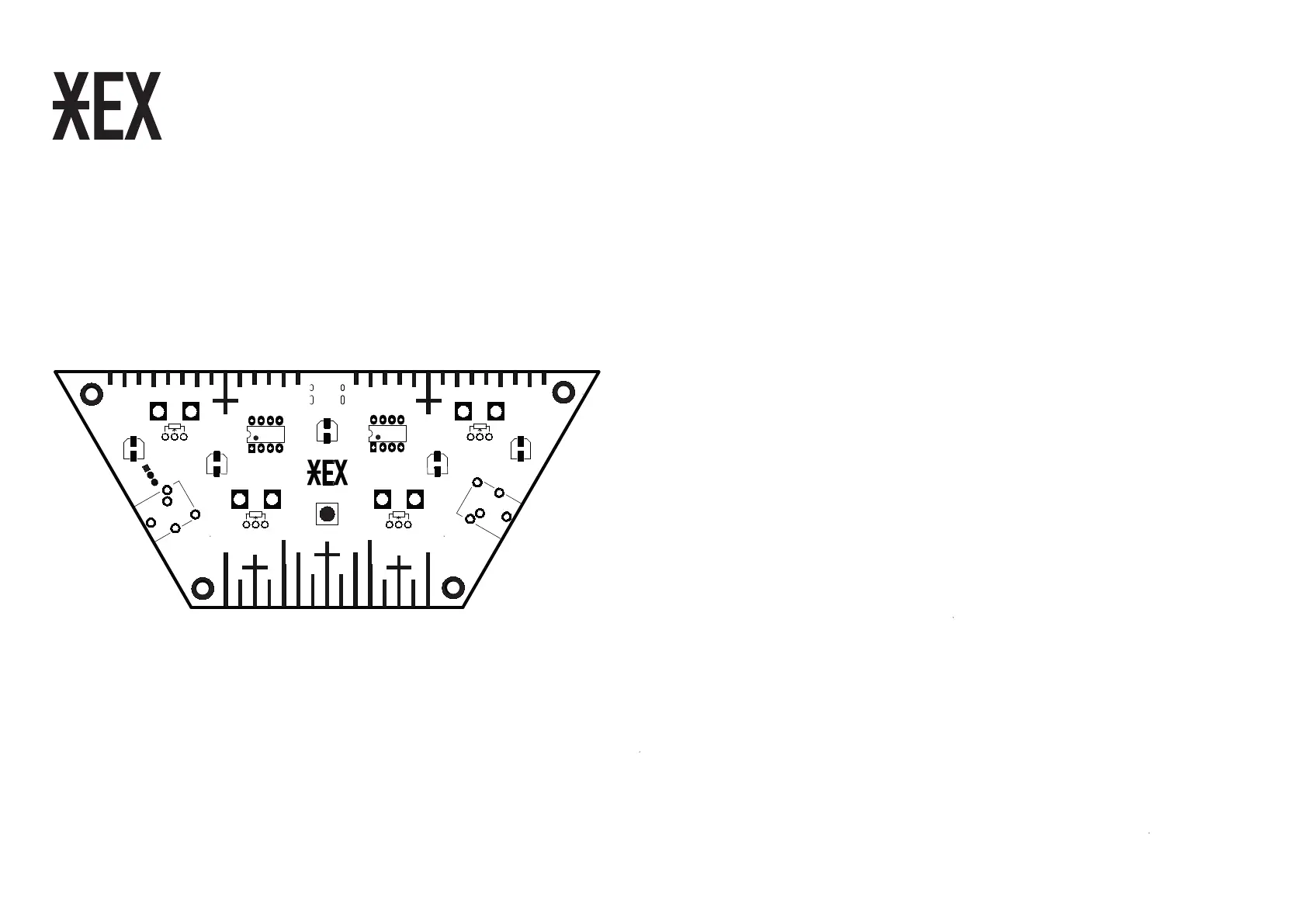
COMPONENTS
1. 47uF capacitor / 1x
2. 10uF capacitor / 2x
3. 1uF capacitor / 2x
4. Header pins / 1x
5. Push button / 1x
6. 3.5mm jack / 2x
7. NE5532 chip / 1x
8. ATTINY85 chip / 1x
9. Potentiometers + knobs / 4x
10. Nuts + bolts / 4x
11. PCB + wooden base / 1x
ASSEMBLE
You will need a soldering iron, solder, pliers, tweezers and some patience. Before you begin the process,
make sure you are working on a clean, well-lit surface. Be careful with the components, some of them are
very small: take them out of the packaging one at a time, when needed. Most of the tiny SMD components
are marked with numbers that match the numbers printed on the PCB. If you are new to soldering (SMD),
we recommend watching some online tutorials beforehand. For the assembly video, visit our website. In any
case, take it slow, go step by step and enjoy the process of building your own HEX. It’s like a puzzle that you
can use and play with afterwards. Oh, and if you have any questions, do not hesitate to contact us. Have fun!
- Solder the 47uF capacitor / 1x *
- Solder the 10uF capacitor / 2x *
- Solder the 1uF capacitor / 2x *
- Solder the 3 pin header on the bottom of the PCB / 1x (align to indent on the wooden base)
- Solder the push button / 1x
- Solder 3.5mm jack / 2x
- Solder the NE5532 chip / 1x *
- Solder the ATTINY85 chip / 1x *
- Solder potentiometers / 4x - (do not put the knobs on before you are finished with the whole process)
- When finished soldering, check if all of the solders are well connected to the components.
- Clip all of the excess steel leads on the bottom side and see if it fits the wooden base.
- Drive in the nuts and tighten the bolts.
- Set potentiometers to central position and attach the knobs.
* For the correct alignment observe printed graphics on the PCB.
1
9
2
3
3
2
5
4
6
6
9
9
9
GAIN RATE
SPREAD
FEED
8
7
 Loading...