Electrical Connection
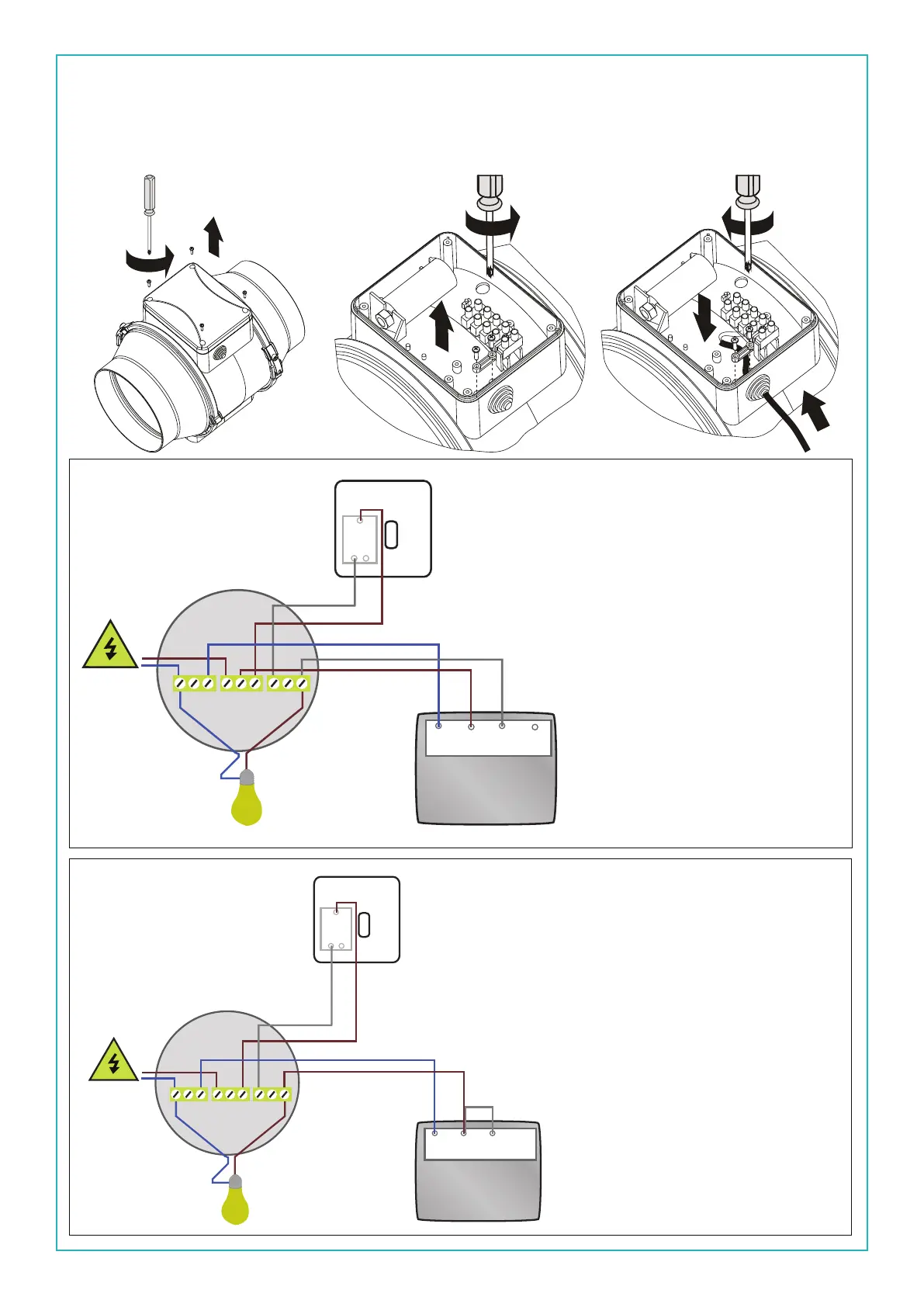
Ensure the mains power supply to which the fan is being connected to is turned off. This product is designed
to be connected to an on/off switch outside the bathroom, or to a celing mounted pull cord switch. Please
follow the visual aids below for wiring the fan.
Once the cover has been taken off
then you can Install the fan wires
into the terminals. The fan should
be wired as follows:
N= Black or Blue L= Brown LT=
Grey .
See image le.
Alternatively if you only have a
two core cable, you can wire the
fan up as follows:
N= Black or Blue L= Brown now
you can loop from the L to the LT.
This does bypass the timer func-
tion. The fan will now only oper-
ate as an on/off fan.
See image le.
L1
L2
C
LT L1LN
N
L
LOOP
Power Supply
Wall Switch
C
e
i
l
i
n
g
R
o
s
e
Fan
Earth connection has
been removed for
illustration purposes only
LT L1LN
Fan
L1
L2
C
N
L
LOOP
Power Supply
Wall Switch
C
e
i
l
i
n
g
R
o
s
e
Earth connection has
been removed for
illustration purposes only
1. 2. 3.


 To Next Page