- 9 -
Figure 3-3 track Equipment grounding
Figure 3-4 track Ground completion schematic
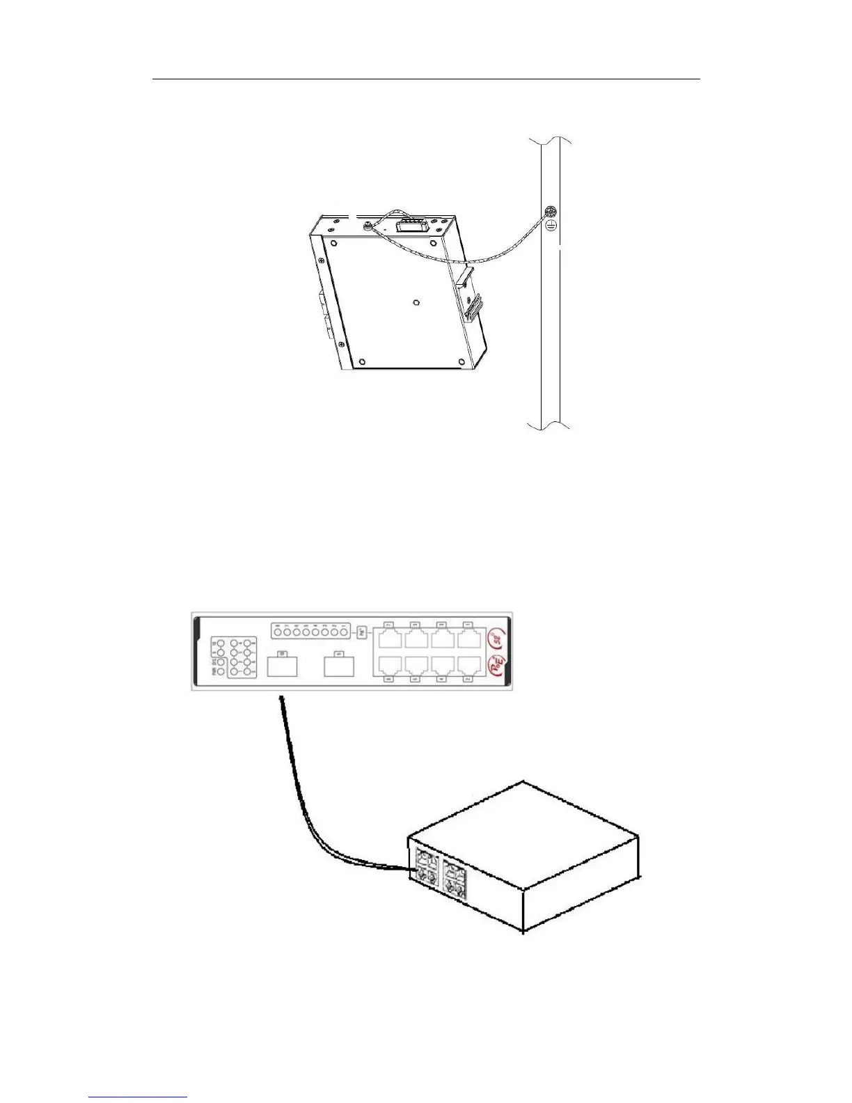
3.4 Connecting the SFP Ports
4/8 switch provides 2 gigabit SFP optical ports. Each port corresponds to one indicator
respectively, which is used for indicating the port Link/ACT state. When the indicator is always
on, the link is normal; when it flickers, the data receives and forwards. To use the optical port,
you need connect it to the SFP optical module, and then to other Ethernet terminal devices
through an optical fiber.
(
Take 8 switch as an example
)
Figure 3-5 Connecting the SFP ports and other Ethernet terminals
 Loading...