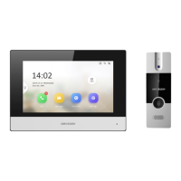
DS-KIS303-P
Video Intercom Kit
UD34406B
Diagram References
1
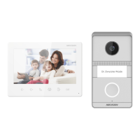
Appearance
DS-KH6320-WTDE1
Network Indoor Sta�on
42
Network Interface 12 VDC Power Interface Alarm Input/Relay Output/
Rs-485 Interface
Four-Wire TerminalsMicrophone
5 6 7
There are 10 pins in the terminal on the rear panel of the indoor sta�on: 2 GND pin, 2
alarm input pins, 4 relay output pins and 2 RS-485 pins.
The are 2 Four-wire terminals on the rear panel of the indoor station to connect
doorphones.
3
It supports wall moun�ng. There are two installa�on modes.
Installa�on Accessory Descrip�on
The wall moun�ng plate and junc�on box are required to install the indoor sta�on onto
the wall.
The dimension of junc�on box should be 75 mm (width) × 75 mm (length) × 50 mm
(depth). The dimension of wall moun�ng plate is shown.
Wall Moun�ng with junc�on Box
Make sure the device in the package is in good condi�on and all the assembly parts
are included.
The power supply the indoor sta�on supports is 12 VDC. Please make sure your power
supply matches your indoor sta�on.
Make sure all related equipments are power-o during the installa�on.
Check the product specica�on for the installa�on environment.
Before You Start
1. Chisel a hole in the wall. The size of the hole should be 76 mm (width) × 76 mm
(length) × 50 mm (depth).
2. Insert the junc�on box to the hole chiseled on the wall.
3. Fix the wall moun�ng plate to the junc�on box with 2 screws.
4. Hook the indoor sta�on to the wall moun�ng plate �ghtly by inser�ng the plate
hooks into the slots on the rear panel of the indoor sta�on, during which the lock catch
will be locked automa�cally.
Wall Moun�ng without junc�on Box
1. Insert 2 expansion tubes into the wall.
2. Fix the wall moun�ng plate to the junc�on box with 2 screws.
3. Hook the indoor sta�on to the wall moun�ng plate �ghtly by inser�ng the plate
hooks into the slots on the rear panel of the indoor sta�on, during which the lock catch
will be locked automa�cally.
Getting Started
4
31
Installation
microSD Card SlotScreen
Note: The appearance of the device varies according to dierent models. Refers to the actual device for
detailed informa�on.
Terminal and Wiring
2
Serial Port (For Debugging Use Only)
8
11
3
3
Rear Panel (without Interface)
Lock Catch Lock Catch
Lock Catch
Lock Catch
Hook
Hook
Hook
Hook
Screw
Wall Moun�ng Plate Junc�on Box Wall
Scan the QR code to get the
Opera�on Guide for detailed
informa�on.
Scan the QR code to get the
Congura�on Guide for detailed
informa�on.
2
122
Unit:mm
100
64.85
Rear Panel (without Interface)
Lock Catch Lock Catch
Lock Catch
Lock Catch
Hook
Hook
Hook
Hook
Screw
Wall Moun�ng Plate Wall
1 2
4
5
6
3
7
8
RS-485
GND
GND
AIN1
AIN2
NO2
COM2
NO1
COM1
485-
485+
B2+
B1+
V2
V1
A2
A1
G
G
Doorphone 2
Doorphone 1
Alarm Input
Relay Output
Activate Indoor Station
For the first-time use of the indoor station, you will need to finish a quick configuration
following the wizard.
1. Choose Language and tap Next.
2. Set password reset method and tap Next.
- Enter the Reserved Email address, and then you can reset the password by email.
Note: On the security questions setting page, you can tap Change to Reserved Email to modify the
password reset method.
- Tap Change to Security Question. Select 3 security questions from Deficiency List and
enter the answers of the questions, then you can reset the password by answering security
questions.
3. Set Network parameters and tap Next.
- Edit Local IP, Subnet Mask and Gateway parameters.
- Enable Auto Get IP Address, and the device will get network parameters automatically.
4. Congure the Indoor Station and tap Next.
a. Select Device Type and edit Floor and Room No.
b. Tap Advanced to set Community No., Building No. and Unit No.
c. Set the Registration Password.
5. Enable Wi-Fi function and tap Next.
-Select a Wi-Fi and enter the password to link.
6. Set Time parameters and tap Next.
7. Slide to enable the Mobile Client Service. Tap Next.
8. Link related devices and tap Next.
-If the device and the indoor station are in the
same LAN, the device will be displayed in the list. Tap the device or enter the serial No.
to link.
9. (Optional): Enable Indoor station and link related indoor extension devices. Tap Finish.
-If the indoor extension and the indoor station are in the same LAN, the device will be
displayed in the list. Tap the device or enter the serial No. to link.
10. Tap Finish to save the settings.
1. Power on the device via 12 VDC power supply or standard PoE. It will enter the
activation page automatically.
2. Create a password and conrm it.
3. Tap OK to activate the indoor station.
1. Tap Settings → → Configuration, and enter admin (activation) password.
2. Tap to enter the device management page.
3. Tap Main Door Station to pop up the device information dialog.
4. Tap the target main door station to link.
Up to 2 analog doorphones can be connected to the indoor station with four-wire
cables. Multiple functions, live view and remote door unlocking for example, can be
realized via operations on the indoor station or Hik-Connect App.
You are required to activate the device rst by setting a strong password before
you can use the device.
Quick Conguration
Connect to Analog Doorphone
Connect to Main Door Station