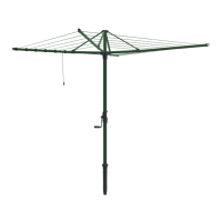
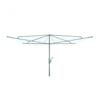
HILLS HERITAGE
™
HOIST
MODELS 4, 5 & 6
OWNERS MANUAL
IMPORTANT: READ OWNERS MANUAL AND
WARNINGS BEFORE ASSEMBLING AND
USING THIS PRODUCT.
“PATENTS & REGISTERED DESIGNS
APPLY TO THIS PRODUCT”
ASSEMBLY INSTRUCTIONS
1. Select a suitable site near to the laundry with about 1 metre clear on all sides of the area covered by the hoist. Dig
a hole 800mm deep and 200mm in diameter. Place 150mm dry gravel in hole, and then the Main Standard (287).
NOTE: Indents downwards.
2. Stand the MAIN STANDARD upright to check convenient height for operator. Add or remove gravel so that teeth of
Reducer (269) is about 75mm above the head.
3. Mix concrete to the following proportions: 3 GRAVEL :2 SAND : 1 CEMENT. IMPORTANT - CONCRETE MUST BE
MIXED FAIRLY DRY. OTHERWISE THE MAIN STANDARD WILL NOT STAY ERECT.
4. Concrete the Main Standard in position and ram the concrete tight. Check for perpendicular. Slope the surface away
from the post to provide for water run-off. Finish off with fine cement.
DO NOT USE FOR 48 HOURS - SO THAT THE CONCRETE MAY HARDEN PROPERLY.
5. Fit CROSS (295) to SECONDARY STANDARD (289) and secure 465mm from TOP of Secondary Standard to TOP
of Cross. Use Set Screw 13” making sure to position bolt hole in Cross (295) directly below bolt hole in TOP of
Secondary Standard (289).
DO NOT FULLYTIGHTEN SCREW YET.
6. Fit top cap lower assembly (292) to secondary standard (289) using screw “56” and nut “E”.
7. Fit tube stay (290) to “TEXTURE MARKED” staple on arm (294) using screw “57” and nut “E”.
8. Fit arm and stay assembly (STEP 7) to hoist by placing arm into cross (295) then stay (290) into top cap assembly
(291 and 292) using screw “55”.
DO NOT SCREW NUT ON YET.
9. Repeat Steps 7 and 8 for other three arms.
10. INNER STAYS (296) supplied for models 5 and 6, are hooked into the innermost staples on arms (294) and
positioned UNDERNEATH the Top Cap lower assembly (292). Fit nut “E” to screw “55” and tighten all nuts.
11. Fit arm caps (293) to end of arms (294).
12. Unroll the coil of wire (246) and starting with staples nearest to the centre of the HEAD PIECE, commence wiring
through the staples. When wire has gone through all four staples, tie end off on the starting arm (REFER STEP 13).
Taking up the slack, trace back the wire, and at each arm “kink” wire at the staple with thumb (see Diagram) making
sure arms are not pulled out of line with those opposite. Finally cut wire, leaving enough to tie off onto the starting
arm.
13. To tie wire off, pass wire through staple, around arm then using pliers, tension and wind end back around the wire.
14. Repeat Step 12 for all other staples working outwards from the centre.
NOTE: Tie off all wires on the same arm.
15. Ensure that the Bolts and Nuts on the gear-box covers have not worked loose during transition.Tighten if necessary.
16. HANDLE - Remove Screw and re-fit Handle right way round to pinion cover (288) - Lock with screw.
17. Raise the HEADPIECE a few turns, so that it is free to revolve. NEVER LEAVE THE HOIST WITH THE CROSS (295)
AND REDUCER (269) ENGAGED. USE THIS BRAKE ONLY WHEN PEGGING OUT AND TAKING IN.
18. Lubricate as per HELPFUL HINTS Instruction 6.
BOLT CHART