2 Installation
2.1 General warnings
! Not to install centers it them in places exposed to extreme temperatures or the inclemencies.
! For a solid and reliable implantation, he is indispensable to make sure that the superficial ones of the
wall are flat.
! To fix centers it them to a height that allows an easy access to the frontal panel.
! Centers is protect they against the manomissioni, but the installation in a protected premises and
eventually in the zone of cover of a volumetric detector is one additional protection.
! The connections to morsettiere go carry out to you after the assembly of the equipment.
! The connections go execute norm CEI 79-3 second "particular Norms for the systems antieffrazione,
antiintrusione, burglar alarm and antiaggression".
2.2 Power supply
It ‘s important to know that the entire system is powered exclusively by the 12V 7,5Ah lead
battery inside of the burglary central unit; the lead battery is constantly in charge by the power
supplier/battery connected to the 230V~ main power supply.
When the installation is finished, it needs to connect the red/black conductors equipped
with faston coming from the power supplier to the battery. Be careful about connection polarity
(Red=positive [+] of the battery; Black=negative [-] of the battery), so that no cause great
damages to the connected devices.
20 21
230V~
50Hz
main
power
supply
Switch
230V~
50Hz
main
power
supply
Switch
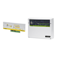
TM series central unit PROTEC series central unit
WARNING!
The main power supply 230V~ has to be connected to the power supplier/battery charger
by two 1,5mm² double-isolation wires coming from a sectioning switch(i.e. a magneto-
thermic protection switch) used exclusively for the burglary central unit. Inside of the
central unit positioning orderly the two wires, locking them by wrappers
TM series central unit/ PROTEC series central unit
Installation
1.3 Technical features
Serie TM / Serie PROTEC burglary central unit - User’s manual
Protection zones immediate zone
Protection zones delayed zone
Protection zones for antisabotage "24h”
Power supply voltage
Service output voltage
Normal current absorption
Max current absorption (only central unit)
230Vca ±10% 50Hz (AL5 included - 1A)
2 7 72 4
13Vdc ±5%
13Vdc ±5%
1
1
Max current supplied by power supplier
Buffer battery
Transformer primary fuse
Dimensions (W)
Dimensions (H)
Dimensions (D)
12V 7Ah
1A - F
Transformer secondary fuse
Fuse on service output voltage
Fuse on sirens output
250mA - F
2A - F
3A - F
280mm
230mm
96mm
285mm
95mm
17mm
External box
ABS Iron
1A (AL5)
40mA
50mA
35mA
3A (with batteriy connected)
650mA
Max current supplied on sirens output
Max current supplied on service output
Box protection level IP30
140mA
Max current absorption
Ambiental class
Safety degree
2
1
Approved directives
CEI EN 50131-1
PROTEC4
PROTEC9
TM500PTM400P
TM900P
antitearing protection tamper
security security