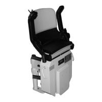
Install the upper stop in the same way as the lower
stop. Fit the long magnet approx. 120 mm before
the (round) lift stop magnet. After the learning run
has been carried out, the lift always stops at the
centre of the round magnet. Position the charging
bars (positive pole at the top/negative pole at the
bottom) at the "centre of the charging pins" and
connect them to the charger unit.
As you can see from the picture, only the positive
cable is connected to the upper charging bar. The
negative cable is connected straight to the guide
rail track from the charger unit.
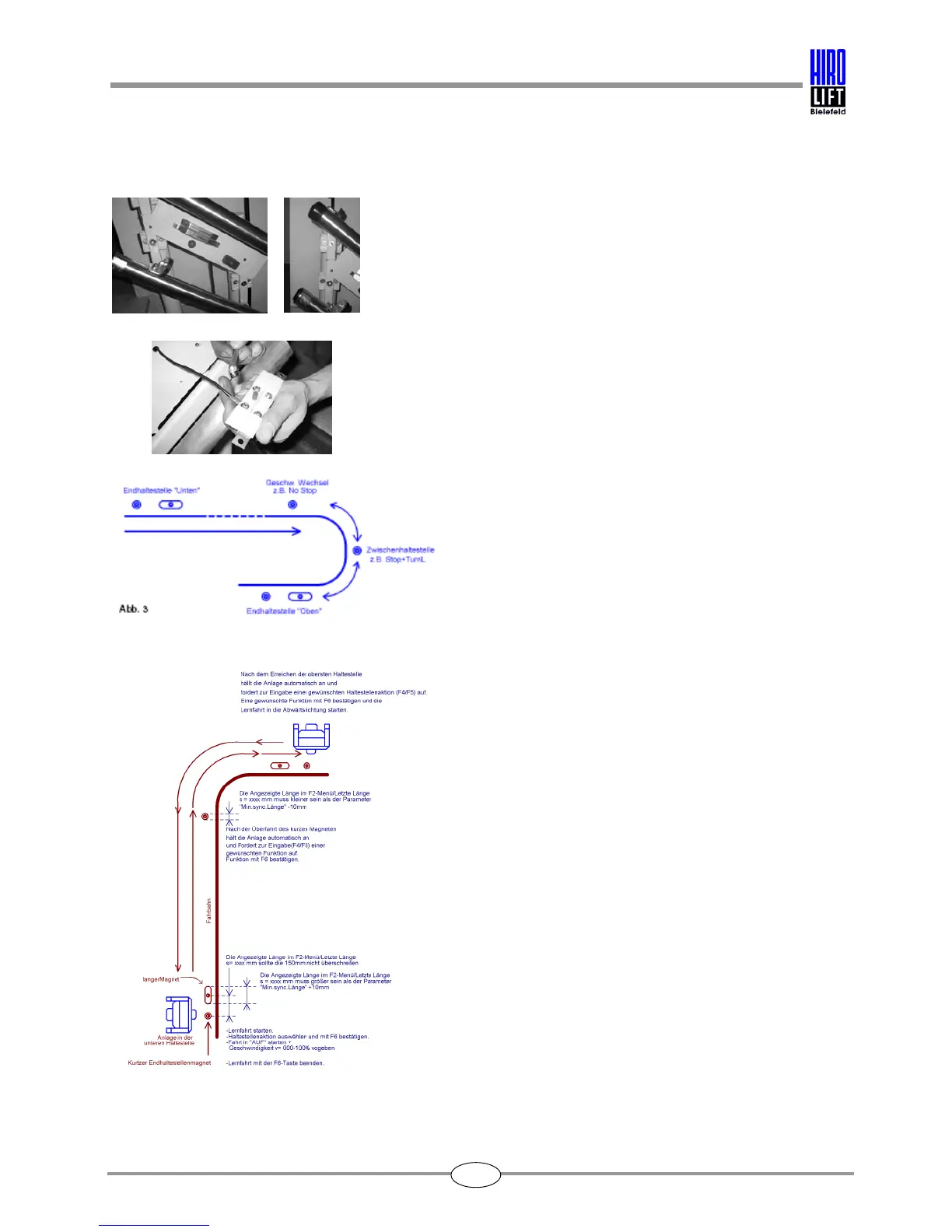
Install all intermediate stops and charging points in
just the same way; for the stopping position, only a
round magnet must be affixed.
A round magnet must be affixed before and after
bends in order to reduce the speed at bends.
Attach all magnets with the brass screws provided.
After all magnets have been positioned and
attached, the learning run can be carried out.