3
D GB F
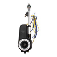
Einbauanleitung
• Die Antenne kann in Wagen mit 12V Batte-
rie ( Minus an Masse ) im spritzwasserge-
schützten Bereich des Radkastens oder im
Kofferraum eingebaut werden.
• An der Einbaustelle ein Loch mit Ø 20 mm
einarbeiten. Die Neigung der Karosserie
kann dabei bis 38° betragen.
• Bei vorhandenen Bohrungen mit Ø 16,5 mm
kann der serienmäßige Antennenkopf ver-
wendet werden. An der Wippe 5 müssen
dazu die beiden Stege abgebrochen werden.
Die Neigung der Karosserie kann dabei bis
ca. 26° betragen.
• Für den Einbau in schmale Kotflügel, bzw.
in stärker geneigte, können die auf der
Verpackung angezeigten zusätzlichen
Antennenköpfe verwendet werden, wobei
der Distanzring 7 teilweise entfällt.
• Das Karosserieblech auf der Unterseite
um die Bohrung herum blank machen und
mit Kontaktschutzfett bestreichen.
Dadurch wird eine gute Masseverbindung
für die Abschirmung und Schutz vor Kor-
rosion erreicht.
• Von der Antenne die Teile 1, 2, 3 und 4
abnehmen. Die Transportscheibe entfer-
nen und den Kunststoffschlauch 8 am
Antriebsgehäuse aufstecken.
• Das beiliegende Antennenkabel am Anten-
nenstutzen aufschrauben.
• Die Antenne von unten in die Karosserie
einsetzen. Die Wippe 5 in der Schale 6 auf
dem Distanzring 7 so drehen, dass sie
rund um die Bohrung anliegt.
• Die Halbkugel 3 mit der Dichtunterlage 4
von oben durch die Bohrung in der auf der
Unterseite anliegenden Wippe 5 einfügen.
• Die Halbschale 2 und die Mutter 1 aufset-
zen. Die Mutter leicht anziehen.
• Die Antenne ausfahren und das Teleskop
ausrichten. Zum Ausfahren das blau/rote
Motorkabel mit dem Plus-, das gelbe mit
dem Minuspol der 12 V Batterie verbinden.
Die Haltelasche 11 entsprechend biegen,
am Antriebsgehäuse festschrauben 10 und
mit der Blechschraube 9 an der inneren
Karosserie bzw. einer Verstrebung befesti-
gen.
• Die Mutter 1 am Antennenkopf anziehen
(max. 4 Nm).
• Das Antennenkabel und die Motoran-
schlussleitungen verlegen. Karosserie-
durchführung für Kabeltülle bohren (Ø 12-14
mm) und zur Abdichtung die Kabeltülle 12
einsetzen.
• Der elektrische Anschluss erfolgt über das
beigefügte Relais mit 2 Wechslern 14,
welches zwischen Antenne und Autoradio
an geschützter Stelle im Wageninnern,
befestigt wird. Dabei muss der Befesti-
gungsbügel des Relais mit der Fahrzeug-
masse elektrisch leitend verbunden werden.
• Die Leitungen entsprechend der Farb-
zeichnung zusammenstecken.
Bei Heckeinbau ist zusätzlich der
Verlängerungskabelsatz HIT AUKAB 420,
Bestell-Nr. 820 640-001 (4 m lang) erfor-
derlich. Dabei werden die elektrischen
Anschlussleitungen bei 15 getrennt und die
Verlängerungsleitungen dazwischen
gesteckt.
Den längeren Schlauch zur sicheren Wasser-
ableitung aus dem Kofferraum durch den
Wagenboden verwenden.
Installation instructions
• The antenna can be installed in cars with a
12V battery (minus connected to ground)
in an area of the wheel housing which is
protected against splash water or in the
trunk.
• Drill a 20 mm (13/16") dia. hole in the car
body at the installation point. At that spot
the inclination of the car body must not
exceed 38°.
• For existing holes of 16.5 mm dia. the
stan-dard aerial base can be used. Pre-
viously the two bars at the lower spherical
half 5 should be broken off. In this case
the car body inclination can be about 26°.
• For installation into narrow or more inclined
fenders the aerial bases marked on the
packing can be used additionally. In some
cases the spacer 7 can be omitted.
• Please bare the body sheet underneath
around the hole and cover it with protecting
grease. Thus a satisfactory ground
connection for the aerial cable screening
and protection against corrosion is ensured.
• Remove from the aerial base the parts 1,
2, 3 and 4. Take away the plastic cover 8
at the end of the motor housing and put
on the drain tube to the motor housing.
• Screw on the enclosed aerial cable to the
socket of the aerial base.
• Insert the aerial from underneath into the
hole. Please see that the lower spherical
half 5 has full contact around the hole.
Slide the sealing washer 4 and the upper
spherical half 3 over the telescopes and
take care that the upper spherical half 3
coincides with the lower spherical half 5 .
• Put on the adapting cover 2 and the hexa-
gonal nut 1. Tighten the hexagonal nut
slightly.
• Drive out the telescopes and adjust the
aerial to the desired direction and inclina-
tion. For driving out the blue/red motor
cable must be connected to plus and the
yellow motor cable to minus of the 12 volt
battery.
• If necessary bend the supporting bracket 11,
screw it to the motor housing 10 of the
aerial by use of screw 9 to the splash
shield or a brace.
• Tighten now the hexagonal nut 1 by means
of a socket wrench (max. 4 Nm).
• Lay the aerial cable and the motor cables.
Drill a hole into the car body for the grom-
met (12-14 mm, 8/16-9/16" dia) and insert
the grommet 12 for sealing.
• Connect the two motor cables with the
enclosed relay having two change-over
switches 14, which is to be mounted bet-
ween aerial and car radio at a protected
place inside the car or the motor compart-
ment. Take care that the fixing bracket of
the relay is connected to the chassis.
• Connect the cables according to their
colouring.
For rear mountinq the extension cable set
HIT AUKAB 420, ord. code 820 640-001
(length 4 m) is additionally required. Thereby
the electrical cables are to be disconnected
at 15 and then the extension cables inter-
connected. Use the longer tube to ensure
water drain off the trunk through the car
body hole.
Instruction de montage
• Vous pouvez installer l'antenne dans les
voitures alimenté avec un batterie de 12 V
(pôle négatif à masse), dans la caisse de
roue qui est protégé contre les éclabous-
sures ou dans le coffre.
• Percez à l'endroit prévu pour le montage
de l'antenne (cet endroit pouvant être in-
cliné à 38° maxi.) un orifice de 20 mm de
diamètre.
• La tête d'antenne standard peut être uti-
lisée dans les perçages de 16,5 mm de Ø.
A la bascule 5 les deux barrettes doivent
être rompues. L'inclinaison de la carrosserie
peut être jusqu'à 26° env.
• Pour le montage dans une aile de voiture
étroite, resp. dans une aile plus fortement
inclinée, les tètes d'antenne supplémentaires
indiquées sur l'emballage peuvent être
utili-sées. L'anneau de distance 7 n'est
pas tou-jours nécessaire.
• Sur la face intérieure de la carrosserie,
mettez la tole à blanc autour du perçage
et prenez soin de l'enduire impeccable-
ment de la graisse de contact. Vous assu-
rez ainsi à la fois un parfait contact de
masse pour le blindage et une protection
anti-corrosive efficace.
• Retirez de l'antenne les pieces 1, 2, 3 et 4,
ainsi que la protection (necessaire pendant
le transport) et mettez en place le
tuyau 8 sur le boîtier du moteur.
• Visser le cable d'antenne joint au manchon.
• Introduisez l'antenne par le bas dans l'ori-
fice de la carrosserie et tournez la pièce
basculante 5 dans son logement 6 jusqu'à
ce qu'elle épouse parfaitement sur l'anneau
de distance 7 la paroi intérieure de l'orifice.
• Mettez en place par le haut, la demi-spère 3
et le joint 4 et ajustez-les, à travers l'orifice,
à la pièce basculante 5.
• Glissez la demi-coquille 2 et l'écrou 1 sur
l'antenne et serrez légèrement.
• Déployez le télescope et orientez-le de
sorte qu'il ait la direction et l'inclinaison
voulues. Reliez pour cela le câble
bleu/rouge au pôle positif et le câble jaune
au pôle negatif de la batterie 12 V et met-
tez le boîtier à la masse.
• Pliez la bride de fixation 11 – au besoin – en
fonction de l'endroit de fixation et vissez-
la sur le boîtier 10. Fixez l'autre bout de la
bride avec la vis Parker 9 sur la partie
intérieure de la carrosserie ou sur un ren-
fort.
• Serrez à fond l'écrou 1 sur la tète de l'an-
tenne (max. 4 Nm).
• Posez les câbles d'antenne et d'alimentati-
on du moteur. Percez un trou de Ø 12 à 14
mm pour le passage des câbles et mettez
en place le passe-câbles 12 pour assurer
l'étanchéité.
• La connexion électrique s'effectue par le
relais à 2 inverseurs joint 14. Montez
celui-ci à un endroit protégé et de manière
à ce qu'il soit placé entre l'antenne et le
poste de radio. La bride de fixation du
relais doit être mise à la masse du véhicule.
• Branchez les conducteurs d'après leurs
couleurs.
Pour montage à l'arrière, le jeu de câble de
rallonge supplémentaire HIT AUKAB 420,
Ref. No. 820 640-001 (4 m de longueur) est
obligatoire. En outre, les conduites de rac-
cordement électriques seront séparées à 15
et les conduites de rallonge enfichées, inter-
calées. Pour avoir une conduite d'eau sûre,
passer le plus long tuyau depuis le coffre
par le plancher de la voiture.
 Loading...