Do you have a question about the Hisense AUV-24UR4SAA1 and is the answer not in the manual?
Details features like space saving, efficiency, timers for Duct, Cassette, and Ceiling/Floor units.
Table showing model availability across Duct, Cassette, and Ceiling/Floor types.
Explanation of the coding system used to identify specific air conditioner model configurations.
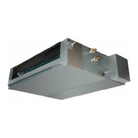
Visuals and model names for Duct, Cassette, and Ceiling/Floor type indoor and outdoor units.
Illustrates and describes the indicators and functions of the display panel for Cassette units.
Technical data for duct units: power, capacity, input, current, and compressor details.
Technical data for cassette units: capacity, input, current, and compressor specifications.
Specifications for ceiling and floor units: capacity, input, current, and compressor details.
Dimensional drawings and measurements for indoor units: Duct, Cassette, and Ceiling/Floor types.
Dimensional drawings and measurements for various outdoor unit models.
Schematic diagrams illustrating refrigerant flow for different unit capacities.
Guidelines for max refrigerant pipe length and height difference for optimal performance.
Wiring diagrams for 18K/36K and 48K/60K models, including recommended wire sizes.
Charts showing airflow and ESP relationships for 18K and 24K duct type units.
Cooling capacity curves for units at various temperatures and capacities.
Detailed wiring diagrams for indoor units (Duct, Cassette, Ceiling/Floor) and outdoor units.
Illustrations and identification of components on indoor and outdoor unit control boards.
Configuration settings for outdoor unit DIP switches for different models.
Instructions on using digital display switches to check operational parameters.
Procedure for changing the static pressure setting for duct type indoor units.
Guide to adjusting internal control parameters via remote controller or buttons.
Tables detailing resistance values for temperature sensors at various temperatures.
Details controller functions: emergency switch, timer, sleep, high power, mute, and cooling wind prevention.
Describes outdoor unit control functions: anti-freeze, overload, exhaust temp protection, oil-return, operation modes.
Information on checking and interpreting fault codes displayed on indoor units for various types.
Guide to understanding fault codes indicated by outdoor unit lamps and digital displays.
Explanation of fault codes displayed via driver board lamps and troubleshooting.
Procedure for checking the refrigerant system using pressure gauges and temperature readings.
Wiring diagrams and resistance values for testing indoor and outdoor fan motors.
Methods for examining and testing compressor circuits and components for various models.
Procedures for testing Inductance, Step Motor, Fuse, and Capacitor using a multimeter.
| Refrigerant | R410A |
|---|---|
| Voltage | 220-240V |
| Frequency | 50Hz |
| Type | Split System |
| Cooling Capacity | 24000 BTU/h |