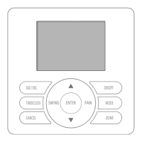
This document describes the Hisense YJE-C01T(E) Central Controller, an optional control component designed for the centralized monitoring and control of air conditioning units. It allows users to manage air conditioners in groups or zones, query and display their operational status on an LCD screen, and set weekly or simple timers. The controller communicates with indoor units and wired controllers via an RS485 communication bus, using shielded twisted pairs with polarity (A+ B-). It can control units either centrally or locally via a wired controller, or centrally via a converter (purchased separately).
Safety Precautions and Important Notices:
The manual emphasizes several safety precautions. Installation should be performed by a dealer or professional to prevent water leakage, electrical shock, or fire. It is crucial to follow the installation manual correctly. Users are warned not to splash water on the appliance or touch it with wet hands due to the risk of electric shock. Tampering with safety devices is prohibited. The main power supply must be cut off before opening the panel for repairs. Specific specification cables must be used and firmly connected to avoid overheating or fire. The appliance must be installed on a base capable of supporting its weight to prevent injury from falling. Electrical supply connection and leakage checks should be performed after installation.
The manual advises against installing the appliance in environments with oil, acid, alkali, sulfide gas (e.g., hot springs), flammable gas, high temperatures, flames, or high-frequency/wireless equipment, as these can cause interference, heat, fire, or damage. Moisture or water flooding can lead to electric shock or electronic parts failure. Spraying pesticides, paint, hair gel, or other toxic gases within 1 meter of the appliance is prohibited. If an Electric Leakage Break (ELB) or fuse trouble occurs, a local service shop should be consulted. Wiring work must adhere to the manual's instructions to prevent electric shock or fire. Objects should not be placed on the unit, and wires/electrical parts must be protected from rodents to prevent damage or fire. Wires must be firmly connected to avoid fire.
For installation, the indoor unit, outdoor unit, wired remote controller, or cables should be at least 3 meters away from high-frequency sources (e.g., medical appliances). Users should not trample or place objects on the products. The wired remote controller should be installed in a location where the average room temperature can be detected, not exposed to direct sunlight, and away from extremely hot or cold locations. Children should not play with the wired remote controller.
Upon receiving the product, it should be inspected for shipping damage, and claims should be filed immediately if any are found. All accessories listed must be included. The model number, electrical characteristics (power supply, voltage, frequency), and accessories should be verified for correctness. The manual explains the standard utilization of the unit, and any other use is not recommended. Local codes and regulations must be followed during installation. The company disclaims responsibility for unauthorized equipment changes.
Function Description and Operation Modes:
The central controller offers two primary operation modes:
- Group Control Mode: Controls all air conditioners within the central control network in a unified manner.
- Zone Control Mode: Controls specific air conditioners within a defined zone in a unified manner.
Before central control, group/zone settings must be configured.
Group Setting:
If a higher-level centralized controller is used, group setting is required. The group number is only relevant for the centralized controller. All air conditioners in the network can be categorized into groups from 1 to 16. To set, hold "ADD. FUNC." for 3 seconds in shutdown state, then use "▲" or "▼" to select the group number, confirm with "ENTER," or cancel with "CANCEL."
Zone Setting:
A maximum of 16 zones can be set in a central control network, with up to 16 air conditioners per zone. To set, hold "ZONE" for 3 seconds until the zone number blinks. Use "▲" or "▼" to select the zone number, then "ENTER." Use "▲" or "▼" to select air conditioner addresses (1-16), confirm with "ENTER," or cancel with "CANCEL." Press "ZONE" again to set the next zone or exit.
Monitoring:
When the central controller is started, the LCD displays the operating state of the air conditioners in the network sequentially if no other operations are performed.
Simple Operation:
The central controller unifies cooling, heating, drying, and air supply functions.
-
Turning ON/OFF:
- Start: Press "ON/OFF" in off state; the ON indicator lights up, and a start command is sent to the group/zone.
- Stop: Press "ON/OFF" in on state; the ON indicator turns off, and a shutdown command is sent. Any set weekly timer ON will take effect.
- Complete Shutdown: Hold "ON/OFF" for over 3 seconds. The controller enters a complete shutdown state (timer ON is disabled, manual start only), the ON indicator turns off, and a shutdown command is sent.
- The ON/OFF button only changes the ON/OFF state without affecting other settings. If a wired controller receives a shutdown command from the central controller, the appliance will enter complete shutdown.
-
Mode Setting:
Press "MODE" to select the desired operation mode (Cooling, Dry, Fan Only, Heating) in ON state or OFF state with a timer set. The mode changes in sequence with each press.
-
Temperature Setting:
Press "▲" or "▼" to set the desired temperature. The temperature setting blinks on the LCD, indicating setting mode. Each press of "▲" increases temperature by 1°C; each press of "▼" decreases it by 1°C. Setting is confirmed 3 seconds after the value stops blinking.
- Range for Cooling, Heating, Drying: 16°C ~ 30°C / 18°C ~ 32°C.
- Fan Only: Temperature cannot be set.
- Note: Heating mode is unavailable for COOLING ONLY models.
-
Fan Speed Setting:
Press "SPEED" to select fan speed (Low, Medium, High, Auto) in ON state or OFF state with a timer set. The fan speed changes in sequence with each press. In "DRY" mode, fan speed is automatically set to "AUTO," and the "FAN" button is ineffective.
-
SWING Setting:
Press "SWING" to select the swing mode (Up/Down SWING, Left/Right SWING, Up/Down/Left/Right SWING, No display/Nothing) in ON state or OFF state with a timer set. This setting is only effective for units with a swing function and specific models.
Function Set:
Clock:
The clock must be set when using the central controller for the first time or after a power loss.
- Upon turning on, date and day of week indicators blink.
- Use "▲" and "▼" to set date, day of week, hour, and minute in sequence. Confirm with "ENTER."
Clock Correction:
Hold "TIMER/CLOCK" for 3 seconds in complete shutoff state to enter clock correction. Adjust settings using the same method as clock setting. After adjustment, press "ENTER."
- Clock correction must be set in complete shutoff state.
- If two central controllers are in the system, only the clock set on the main controller is effective.
- Complete shutoff: Hold "ON/OFF" for 3 seconds.
- Temporary shutoff: Press "ON/OFF" briefly.
- "Shutoff state" in this manual refers to temporary shutoff.
This function prevents accidental operation by children or others.
- Set: Hold "ENTER" for 3 seconds; the buzzer beeps 4 times, and the lock icon appears on the LCD. All operations become invalid, but the controller still operates normally.
- Cancel: Hold "ENTER" for 3 seconds; the buzzer beeps 4 times, and the lock icon disappears.
Simple TIMER ON (invalid under weekly timer set):
- Press "TIMER/CLOCK" when the appliance is off. The timer ON indicator and hour setting blink.
- Use "▲" (increase) and "▼" (decrease) to set the time (1-24 hours, 1-hour resolution).
- Press "ENTER" to confirm. The display returns to the previous state, and the "Timer" indicator appears.
- Can be canceled by "CANCEL" or "TIMER/CLOCK."
- Pressing "TIMER/CLOCK" again displays the remaining time.
- After the set time, air conditioners in the group/zone turn on under unified control.
- Simple timer ON is only set in shutoff mode.
- After setting, mode, temperature, fan speed, and swing mode can be adjusted.
- Simple timer ON is canceled if the appliance is turned on. For continuous effect, set the weekly timer.
- Simple timer ON/OFF cannot be set simultaneously.
- Simple timer ON is only effective for the current group/zone.
Simple TIMER OFF (invalid under weekly timer set):
- Press "TIMER/CLOCK" when the appliance is on. The timer OFF indicator and hour setting blink.
- Use "▲" (increase) and "▼" (decrease) to set the time (1-24 hours, 1-hour resolution).
- Press "ENTER" to confirm. The display returns to the previous state, and the "Timer" indicator appears.
- Can be canceled by "CANCEL" or "TIMER/CLOCK."
- Pressing "TIMER/CLOCK" again displays the remaining time.
- After the set time, air conditioners in the group/zone turn off under unified control.
- Simple timer OFF is only set in on state.
- After setting, mode, temperature, fan speed, and swing mode can be adjusted.
- Simple timer OFF is canceled if the appliance is turned off. For continuous effect, set the weekly timer.
- Simple timer ON/OFF cannot be set simultaneously.
- Simple timer OFF is only effective for the current group/zone.
Weekly Timer:
Allows setting ON/OFF times for seven days a week, with up to four groups of settings assignable to any day. The resolution is 1 minute, and the signal is effective within 1 minute.
- Operation Procedure: Hold "TIMER/CLOCK" for 3 seconds to enter weekly timer setting. The group number blinks.
- Setting:
- First timer group number 1 blinks. Press "ENTER" to enter Timer ON setting.
- Timer ON hour blinks. Use "▲" or "▼" to set the desired time (1-hour resolution). Press "ENTER" to return to minute setting. Press "CANCEL" to skip Timer ON/OFF setting.
- Timer OFF setting is performed similarly.
- After TIMER ON/OFF setting, use "▲" or "▼" to select the desired day(s). Press "ENTER" to confirm; selected days are marked with ".". Press "CANCEL" to cancel.
- After setting for seven days, proceed to group 2 settings (up to four groups).
- Exit weekly timer setting by pressing "TIMER/CLOCK" or "ON/OFF" in group selection mode.
- Checking: Press "TIMER/CLOCK" to check current weekly timer settings. Use "▲" or "▼" to view previous/next set times. Press "TIMER/CLOCK" again to exit.
- To temporarily disable the weekly timer without losing settings, hold "ON/OFF" for 3 seconds to turn off the controller completely.
Other Functions:
Temperature Display Setting:
- Default: Set temperature.
- Display Room Temperature: Press "▲" and "ENTER" simultaneously for 3 seconds. Buzzer beeps 4 times, and the room temperature icon appears.
- Cancel: Press "▼" and "ENTER" simultaneously for 3 seconds. Buzzer beeps 4 times, and the room temperature icon disappears, reverting to set temperature display.
Buzzer Indicator Selection:
- Default: Buzzer beeps during operation.
- Mute: Hold "FAN" for 3 seconds. Buzzer beeps 4 times, indicating successful change.
- Return to Default: Repeat the steps.
Backlight Selection:
- Default: Backlight lights up during operation.
- Turn Off: Hold "MODE" for 3 seconds. Buzzer beeps 4 times, indicating successful change.
- Return to Default: Repeat the steps.
Maintenance, Troubleshooting, and After-Sales Service:
Maintenance:
Wipe the LCD and body of the wired controller with a dry cloth. For stubborn dirt, use a cloth soaked in neutral detergent diluted with water, squeezed tightly, then wipe with a dry cloth. Do not use thinner, organic solvents, or strong acid.
Troubleshooting and After-sales Service:
If the air conditioner malfunctions, an error code will display on the LCD. Note the error code and contact After-sales Service. Consult the dealer for more information.
Installation Instructions:
Important Notice:
Installation must follow these instructions and be performed by professionals.
- Complete documentation for design planning, installation, commissioning, and after-sales services of the central control system must be archived.
- Design planning should include:
- Composition and quantity of controls.
- Selection and installation position of wired controller, electrical distribution, wiring, address assignment, and connection.
- Installation position of central controller, setting of primary/secondary controllers, electrical distribution, wiring, and connection.
- Installation and wiring of the central control system, bus length limitations, terminal-matched resistor at bus ends, and single-point grounding of the shielding layer.
- Notes:
- Central control and distribution cables should not be near each other or in the same conduit. RS485 bus should be routed away from interference sources, especially high voltage sources like transformers and frequency converters.
- Total length of the central control bus should not exceed 1000m (at 9600 bps).
- Appliances at either end of the bus must have a terminal-matched resistor (refer to dip switch settings).
- Single-point grounding of the shielded cable is recommended in the middle of the communication bus, near the central controller.
- Daisy-chain bus arrangement is recommended for central control lines. For star or tree topologies, 485 concentrators and repeaters are recommended.
- Wiring and installation should be performed concurrently with air conditioner installation and commissioning. A test run should be performed before installation.
- Primary and secondary controllers can operate simultaneously in one central control system, with at least one designated as primary.
Checking Accessories:
The packaging box should contain:
- Use and installation instructions (Qty: 1)
- Screw (Qty: 2)
How to Install:
-
Selecting Location: Choose the installation location based on the "Important Notice" guidelines.
-
Removing Upper Cover: Insert a screwdriver into the designated position and gently rotate to remove the upper cover.
-
Connecting the Central Controller:
- Leading-out Line: Pull the power supply line and central control communication line from the embedded terminal box (provided by users) to connect them to the terminal block on the rear cover of the central controller.
- Connections:
- Power supply: 220V ~/50Hz.
- Connect power supply terminal and central control communication terminal (A+, B-) to the central controller.
- Minimum specifications:
- Power supply line (copper core wire): Cross-sectional area 2×0.75mm².
- Central control communication line (shielded twisted pairs): Cross-sectional area 2×0.75mm².
- Ensure correct polarity of communication lines.
- Connecting cords must be reliably secured.
- Securing the Lower Cover:
Install the lower cover onto the embedded terminal box (86 type, field-supplied) using the two provided Phillips M4×20 screws.
Setting Dip Switches:
- Default Setting: SW1 (OFF 1 2 3 4), SW2 (OFF 1 2).
- SW1 (Address Settings):
- Addresses must not be repeated within the same central control system.
- Settings can be made for both primary and secondary central controllers.
- The primary controller has priority, and its position must be set to "OFF."
- SW2 (Setting for Terminal Resistor):
- Set the switch to "ON" at either end of the central control system.
- SW2-1: For central control system.
- SW2-2: For central management system.
Setting Baud Rate:
The default baud rate code is 00, supporting communication up to 1000m. The baud rate may need to be changed for different central control systems to ensure transmission rate.
- Hold "ADD.FUNC." and "ON/OFF" for 3 seconds. Buzzer beeps 4 times, entering self-checking state. Use "▲" to select series number 4, then "ENTER." The baud rate code blinks.
- Use "▲" or "▼" to select the proper code (000: 9600 bps, 1000m; 001: 19200 bps, 400m; 002: 38400 bps, 200m).
- Press "ENTER" to complete the setting.
- Note: The baud rate of the central controller and wired controller/central box must be the same; otherwise, the system will not operate properly.
Resetting the System:
Hold "ADD.FUNC." and "ON/OFF" for 3 seconds. Buzzer beeps 4 times, entering self-checking state. Use "▲" to select series number 3, then "ENTER." When "boot" blinks on the LCD, press "ENTER" to reset the system. All system settings (except dial switches) are restored to factory settings.
Snapping Upper Cover into Place:
Align the upper cover with the corner buckles of the lower cover and press until it snaps into place. Remove the protective sticker after installation.