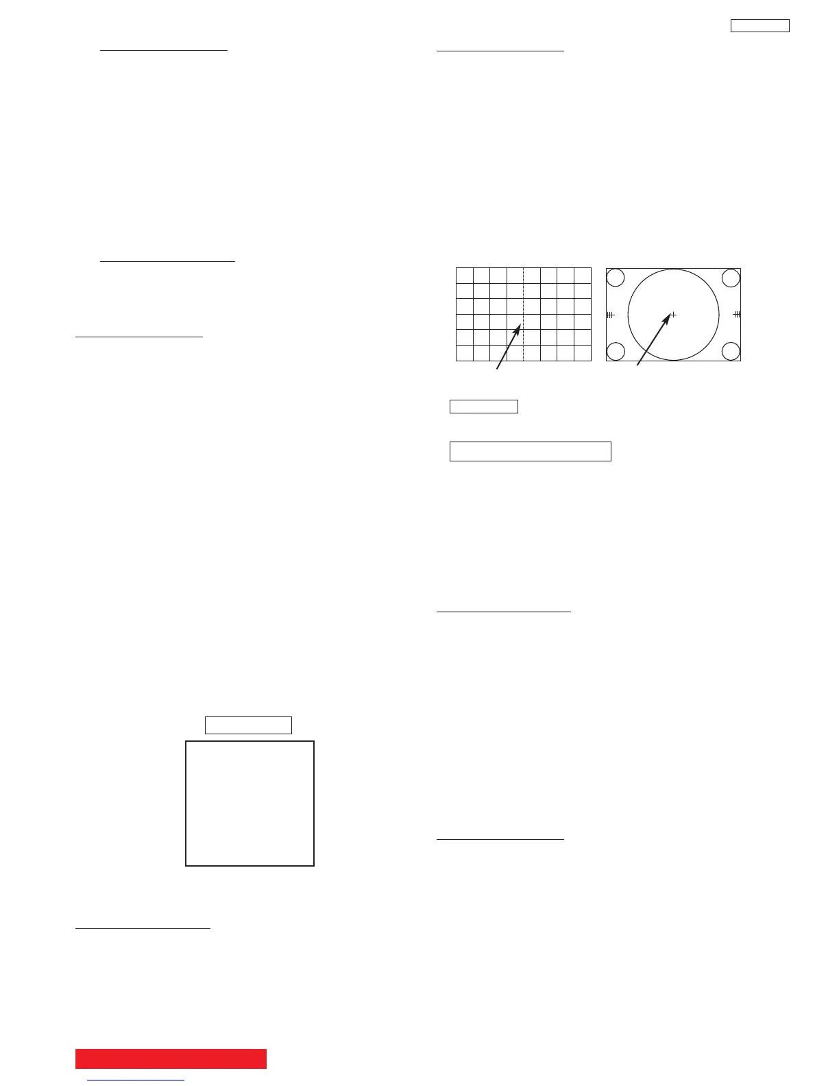
Circle centerDC crosshatch center
DC crosshatch
ATSC or NTSC
Circle pattern
Adjustment procedure
(1) Receive circle pattern.
(2) Push SERVICE ONLY switch to display DC
crosshatch. Mark the DC crosshatch center
position using your finger tip.
(3) Push SERVICE ONLY switch again to exit from
the DC crosshatch.
(4) Go to I
2
C ADJ. mode.
(5) Choose H. POSI item by using up/down
cursor key. Adjust horizontal position to match
the circle center to DC crosshatch center
(marked by your finger tip).
(6) Exit from I
2
C menu.
Remark The “SERVICE ONLY” switch located on
the SIGNAL PWB (SC01).
1080i 16:9 STANDARD
(7) Receive any 1080i Signal (fH=33.75KHz) circle
pattern signal (Input to component video
terminal).
(8) Repeat steps (2)~(5).
(9) Press SELECT key, then H. POS H will appear.
It means HD mode is activated.
(10)Exit from I
2
C menu.
2.4 Raster Tilt adjustment (Deflection yoke)
Adjustment preparation
(1) The set can face east or west.
(2) Input the single cross test signal.
(3) Set CONTRAST to MAX, other controls to
CENTER.
(4) The lens focus and horizontal position
adjustment should have been coarse adjusted.
(5) The electrical focus should have been coarse
adjusted.
(6) The digital convergence RAM should be cleared
(uncorrected state). With the TV set off, press
and hold the “SERVICE ONLY” switch and then
press the power button.
(7) Start adjustment 20 minutes or more after TV is
turned on.
Adjustment procedure
(1) Short-circuit 2p EH (TS) sub-mini connectors on
Red and Blue CPT P.W.B.s to project only the
Green beam.
(2) Turn the G deflection yoke and adjust the
vertical raster inclination.
(3) Then, remove the shorted wire on the 2p EH(TS)
sub-mini connectors on the R or B CPT PWB
and project red or blue light and green light
together on screen.
Adjustment procedure
(1) Cut off adjustment should be finished.
(2) Set video conditions to factory preset.
(3) R/C must be in DCAM mode (see page 47).
Adjustment procedure
(1) Receive any NTSC signal.
(2) Push “SERVICE ONLY” SW (SC01) on SIGNAL
PWB. (Enter to DC ADJ. mode).
(3) Press [FAV CH] key on R/C. (Green cross hatch
is displayed).
Then push EXIT key on R/C. (Character pattern
is displayed. This is the PHASE setting mode).
(4) Set PH-H phase data as shown below by using
[4] and [6] key on R/C.
(5) Set PH-V phase data as shown below by using
[2] and [5] key on R/C.
(6) Set CR-H phase data as shown below by using
CURSOR PAD
F and E key on R/C.
(7) Set CR-V phase data as shown below by using
CURSOR PAD
G and H key on R/C.
(8) Push [FAV CH] key on R/C to exit from the
PHASE mode.
(9) Press ASPECT key 2 times on R/C to write the
phase data to memory.
(10) When Green dots are displayed, push [MUTE]
key to return to DC ADJ. mode.
(11)Push “SERVICE ONLY” SW to return to RF or
VIDEO mode.
Normal Mode
2.3 Horizontal Position Adjustment (Coarse)
Adjustment preparation
(1) DC PHASE DATA SETTING should be
finished.
PHASE MODE: N
PH-H :F2
PH-V: 07
CR-H: 37
CR-V: 14
BACK TO ADJUSTMENTS
33
DP65
(1)
(2) Choose “SERVICE” item from I
2C adjustment
menu by pressing THUMB STICK E.
(3) Screen VR should be turned clockwise gradually
and set so that retrace line begins to appear.
(4) Return to “NORMAL” mode by THUMB STICK
F again.
(5) Adjust Focus VR’s so that focus is even all
around screen.
2.2 Digital Convergence (DC) Phase Data Setting
Adjustment preparation
Press the MENU key on the CONTROL PANEL of
the TV, then press the R/C keys MENU+8+SELECT
to enter adjustment mode.