---------------------------------
LCD-III
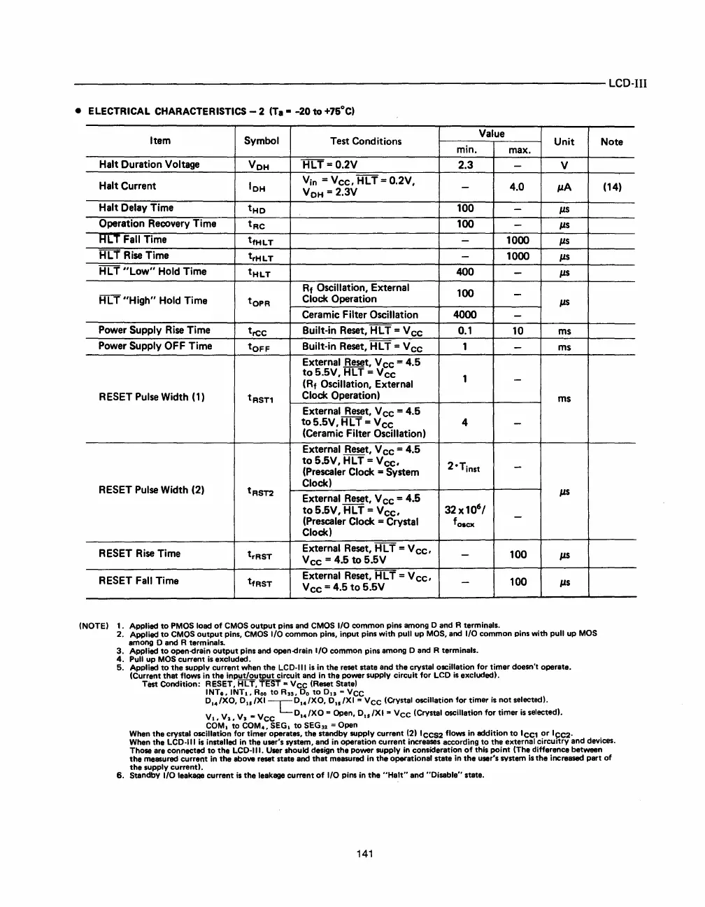
• ELECTRICAL CHARACTERISTICS - 2
(T.
-
-20
to
+7SoC)
Item
Symbol
Test
Conditions
Value
Unit
min.
max.
Halt
Duration
Voltage
V
OH
HLT=0.2V
2.3
-
V
Halt
Current
IOH
Vin =
Vee,
HLT
=
0.2V,
-
4.0
#J.A
V
OH
=
2.3V
Halt
Delay
Time
tHO
100
-
#J.S
Operation
Recovery
Time
tRe
100
-
#J.s
Her
Fall
Time
tfHLT
-
1000
#J.s
HL
T
Rise
Time
trHLT
-
1000
#J.s
HL
T
"Low"
Hold
Time
tHLT
400
-
#J.S
Rf
Oscillation,
External
100
-
HLT
"High"
Hold
Time
tOPR
Clock
Operation
#J.S
Ceramic
Filter
Oscillation
4000
-
Power
Supply
Rise
Time
tree
Built-in
Reset,
HLT
=
Vee
0.1
10
ms
Power
Supply
OFF
Time
tOFF
Built-in
Reset,
H L T =
Vee
1
-
ms
External
Reset,
Vee
=
4.S
to
S.SV,
HLT
=
Vee
1
-
(Rf
Oscillation,
External
RESET
Pulse
Width
(1)
t
R
S
T1
Clock
Operation)
ms
External
Reset,
Vee
=
4.S
toS.SV,
HLT
=
Vee
(Ceramic
Filter
Oscillation)
4
-
External
Reset,
Vee
=
4.S
to
S.SV,
HLT
=
Vee,
20Tinst
-
(Prescaler
Clock
=
System
RESET
Pulse
Width
(2)
t
R
S
T2
Clock)
External
Reset,
Vee
=
4.S
#J.S
toS.6V,
HLT
=
Vee,
32
x
10
6
/
(Prescaler
Clock
=
Crystal
f
o
•
ex
-
Clock)
RESET
Rise
Time
trRST
External
Reset,
HLT
=
Vee,
Vee
=
4.S
to
S.SV
-
100
#J.S
RESET
Fall
Time
tfRST
External
Reset,
HLT
=
Vee,
Vee
=
4.S
to
S.SV
-
100
#J.s
(NOTE
I 1. Applied to
PMOS
load of
CMOS
output pins and
CMOS
I/O
common pins among 0 and R terminals.
2. Applied to
CMOS
output pins,
CMOS
I/O
common pins, input pins with pull up MaS, and
I/O
common pins with pull
up
MOS
among 0 and R terminals.
3.
Applied to open-drain output pins and open-drain I/O common pins among 0 and R terminals.
4.
Pull
up MaS current
is
excluded.
5.
Applied to the supply current when the
LCD-III
is
in
the reset state and the crystal oscillation for timer doesn't operate.
(Current that flows
in
the
input/outPE~Tircuit
and
in
the power supply circuit for
LCD
is
excludedl.
Test Condition: RESET,
HLT,
T ..
Vee
(Reset Statel
INTo, INT.,
Roo
to R
n
,
Do
to 013 =
VCC
D.
4
/XO,
Du
/XI
LD
••
/XO, Du/XI ..
Vee
(Crystal oscillation for timer
is
not selectedl.
V.,
V
2
,
VI
_
Vee
D.
4
/XO = Open,
Du/
XI
'"
Vee
(Crystal oscillation for timer
is
selected
I.
COM.
to COM., SEG. to
SEG
32
= Open
Note
(14)
When
the crystal oscillation for timer operates, the standby supply current (211eeS2 flows
in
addition to lee1
or
lee2.
When
the
LCD-III
is
installed
in
the user's system, and
in
operation current increases according to the external circuitry and devices.
Those are connected to the
LCD·1I1.
User
should design the power supply
in
consideration
of
this point (The difference between
the measured current
in
the above reset state and that measured
in
the operational state
in
the user's
sYstem
is
the increased part of
the supply currentl.
6.
Standby
I/O
leak8A8
current
is
the leakage current
of
I/O
pins
in
the "Halt" and "Disable" state.
141
 Loading...

